Phs communications mode – Epson S1C33210 User Manual
Page 397
III PERIPHERAL BLOCK: MONITORED MOBILE ACCESS INTERFACES
S1C33210 FUNCTION PART
EPSON
B-III-10-11
PHS Communications Mode
Overview
The PHS communications mode works in combination with the software modem module to process PIAFS frames
for data transfers with PHS devices.
For a transmit operation, this mode serially transmits 76 bytes of data from one of two buffers plus a 32-bit CRC
using the frame and clock timing from the PHS device. For a receive operation, it waits for the 32-bit synchronization
pattern and then receives 76 bytes of data and a 32-bit FCS (CRC) into one of two buffers using the frame and clock
timing from the PHS device, checks the FCS (CRC), and stores the results in a register.
This mode sends two types of interrupt requests to the CPU: a PHS transmit interrupt after sending 640 bits of data
and a PHS receive interrupt after receiving 640 bits of data.
For communications macro select (MCRS) register (D[1:0]/0x200000) settings other than 00–that is, HDLC, PDC,
and PHS communications modes–the MOPORT3 and MOPORT2 bits in the communications block output port data
register (D[3:0]/0x020000A) drive the RTS and DTR pins using negative logic.
The MIPORT[1:0] bits in the communications block input port data register (D[1:0]/0x020000C) track the input
levels for the DSR and RI pins.
Signal Format
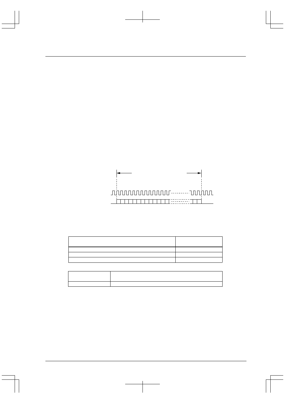
Figure 10.10 summarizes the PIAFS serial data signal format for PHS communications. The data format is the
same in both directions, but there is no phase synchronization between the two bit streams.
32 kbps: 20 ms
@
64 kbps: 10 ms
CTS (PHS clock)
TXD and RXD (serial data)
0 1 2 3 4 5 6 7
(Total 640 bits)
Figure 10.10 PHS Communications Data Format
PIAFS synchronization frames, negotiation frames, and negotiation frames including synchronization frame
functions contain FI codes and SYNC patterns at the positions shown in the following Tables.
Table 10.6 FI Code Types
Frame type
Bit pattern (Bit positions
0 to 3 from start)
Synchronization frame
0 0 0 0
Negotiation frame
1 0 0 0
Negotiation frame including synchronization frame functions
1 0 0 1
Table 10.7 SYNC Pattern
32-bit fixed bit pattern
(Bit positions 24 to 55 from start)
SYNC Pattern
0 1 0 1 0 0 0 0 1 1 1 0 1 1 1 1 0 0 1 0 1 0 0 1 1 0 0 1 0 0 1 1