Control and operation of irda interface, When transmitting, When receiving – Epson S1C33210 User Manual
Page 339
III PERIPHERAL BLOCK: SERIAL INTERFACE
S1C33210 FUNCTION PART
EPSON
B-III-8-23
Control and Operation of IrDA Interface
The transmit/receive procedures have been explained in the section on the asynchronous interface, so refer to
"Control and Operation of Asynchronous Transfer".
The following describes the data modulation and demodulation performed using the PPM modulator circuit:
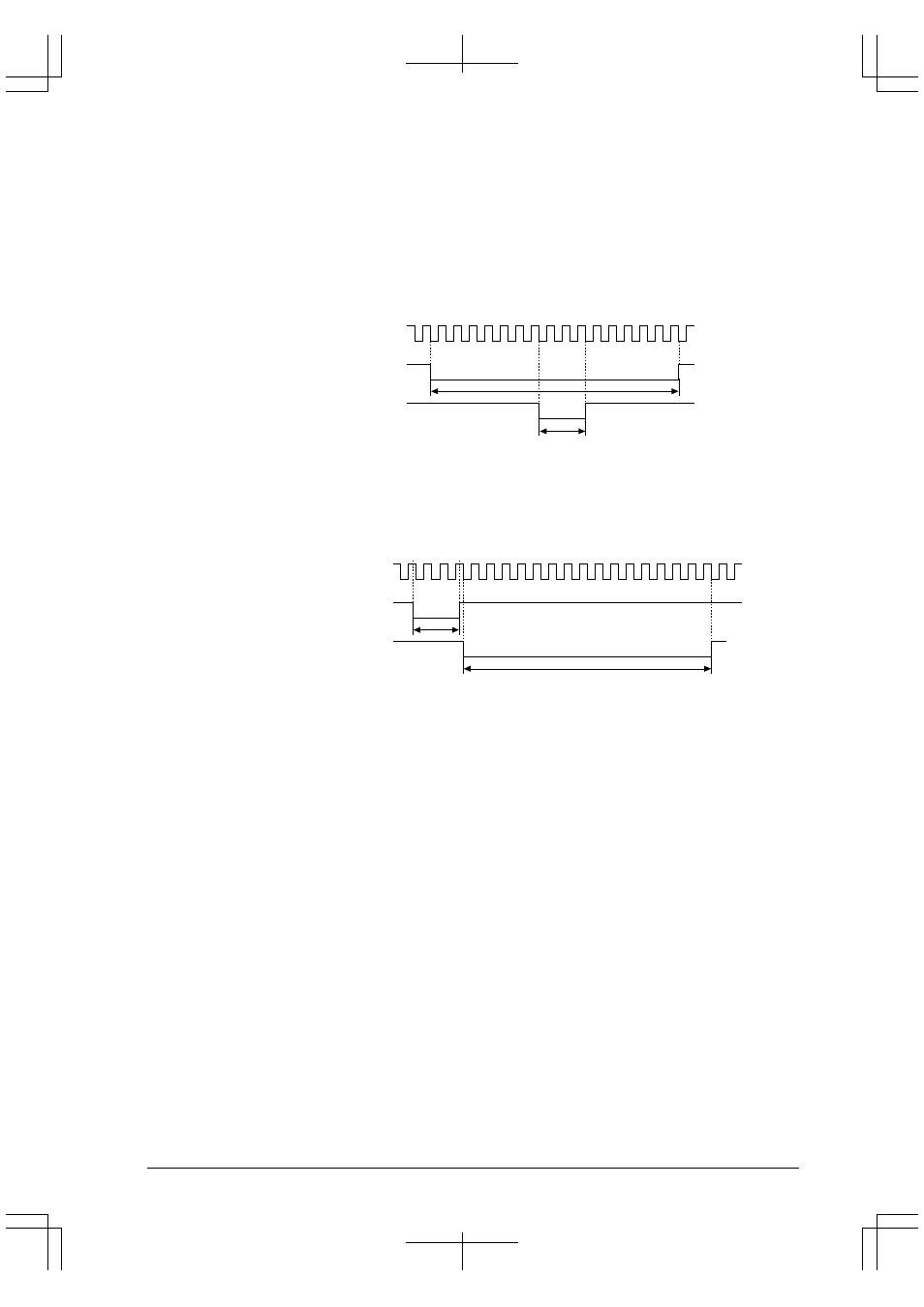
When transmitting
During data transmission, the pulse width of the serial interface output signal is set to 3/16 before the signal is
output from the SOUTx pin.
TCLK
PPM modulator input (I/F output)
PPM modulator output (SOUTx)
1
2 3
8 9 10 11
16
3
×
TCLK
16
×
TCLK
Figure 8.16 Data Modulation by PPM Circuit
When receiving
During data reception, the pulse width of the input signal from SINx is set to 16/3 before the signal is
transferred to the serial interface.
TCLK
PPM modulator input (SINx)
PPM modulator output (I/F input)
1
2 3 4
16
16
×
TCLK
3
×
TCLK
Figure 8.17 Demodulation by PPM Circuit
Note: When using the IrDA interface, set the internal division ratio of the serial interface 1/16 (DIVMDx =
"1"), rather than 1/8 (DIVMDx = "0").