Iii-7 clock timer, Configuration of clock timer – Epson S1C33210 User Manual
Page 305
III PERIPHERAL BLOCK: CLOCK TIMER
S1C33210 FUNCTION PART
EPSON
B-III-7-1
III-7 CLOCK TIMER
Configuration of Clock Timer
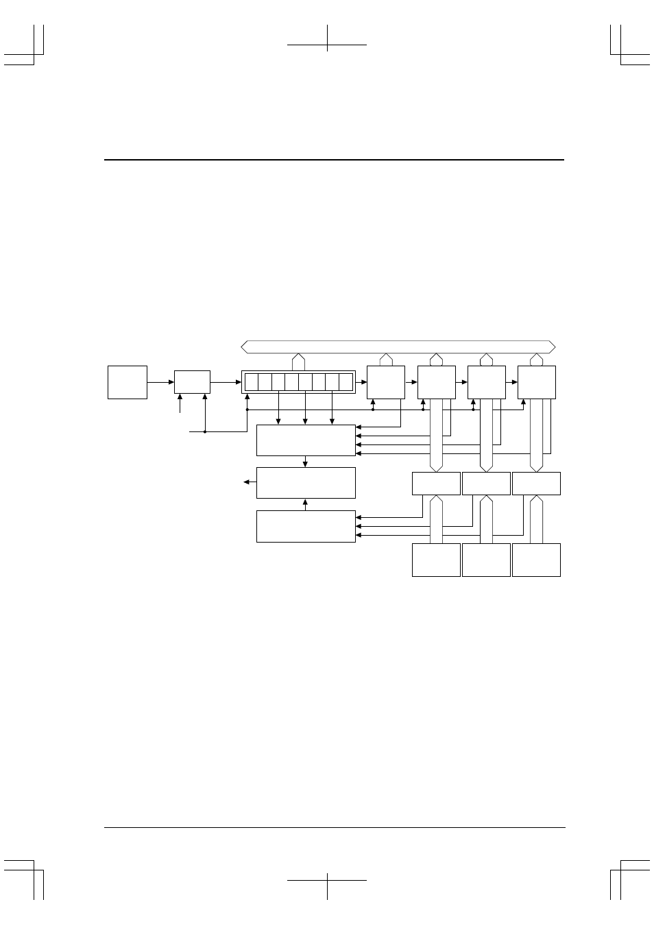
The clock timer consists of an 8-bit binary counter that is clocked by a 256-Hz signal derived from the low-speed
(OSC1) oscillation clock f
OSC1
, and second, minute, hour, and day counters, allowing all data (128 Hz to 1 Hz,
seconds, minutes, hours, and day) to be read out in a software. It can also generate an interrupt using a 32-Hz, 8-Hz,
2-Hz, or 1-Hz (1-second) signal or when a one-minute, one-hour, or one-day count is up, in addition to generating an
alarm at a specified time (minute or hour) or day.
The low-speed (OSC1) oscillation circuit and the clock timer can be kept operating even when the CPU and other
internal peripheral circuits are placed in standby mode (HALT or SLEEP).
Normally, this clock timer should be used for a clock and various other clocking functions.
Figure 7.1 shows the structure of the clock timer.
Note: Since the clock timer is driven by a clock originating from the low-speed (OSC1) oscillation circuit,
this timer cannot be used unless the low-speed (OSC1) oscillation circuit (32.768 kHz, Typ.) is
used.
OSC1
oscillation
circuit
Interrupt generation
control circuit
Interrupt/alarm
select circuit
Divider
Internal data bus
Alarm generation
control circuit
f
OSC1
256 Hz
32.768 kHz
128
Hz
64
Hz
32
Hz
16
Hz
8
Hz
4
Hz
2
Hz
1
Hz
Clock timer Run/Stop
Clock timer reset
Interrupt request
(to interrupt controller)
6-bit
seconds
counter
6-bit
minutes
counter
5-bit
hours
counter
16-bit
day
counter
Comparator Comparator Comparator
6-bit minute
comparison
data
5-bit hour
comparison
data
5-bit day
comparison
data
Figure 7.1 Structure of Clock Timer