Setting external bus conditions, Setting device type and size – Epson S1C33210 User Manual
Page 161
II CORE BLOCK: BCU (Bus Control Unit)
S1C33210 FUNCTION PART
EPSON
B-II-4-9
Setting External Bus Conditions
The type, size, and wait conditions of a device connected to the external bus can be individually set for each area
using the control register (0x48120 to 0x48130). The following explains the available setup conditions individually
for each area. For details on how to set the DRAM interface conditions, refer to "DRAM Direct Interface".
The control register used to set bus conditions is initialized at cold start. Therefore, please set up these registers again
using software according to the external device configuration and specifications.
When the IC is hot-started, the setup contents and pins retain their previous status before a reset.
Setting Device Type and Size
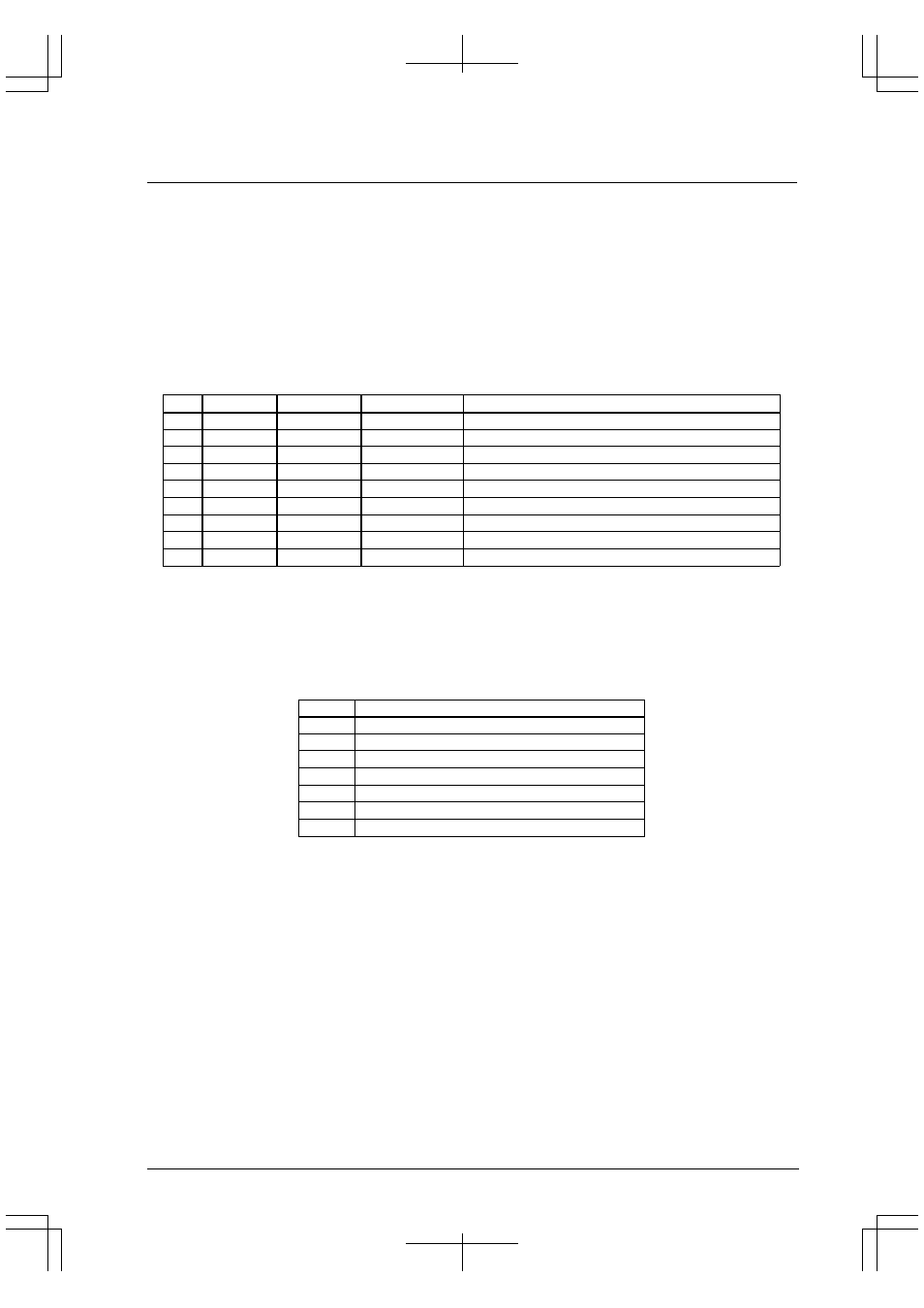
Table 4.7 shows the types of devices that can be connected directly to each area.
Table 4.7 Device Type
Area
SRAM type
DRAM type
Burst ROM type
Control bit
18–15
●
X
X
None
14
●
●
X
A14DRA(D8)/Areas 14–13 set-up register(0x48122)
13
●
●
X
A13DRA(D7)/Areas 14–13 set-up register(0x48122)
12,11
●
X
X
None
10
●
X
●
A10DRA(D8)/Areas 10–9 set-up register(0x48126)
9
●
X
●
A9DRA(D7)/Areas 10–9 set-up register(0x48126)
8
●
●
X
A8DRA(D8)/Areas 8–7 set-up register(0x48128)
7
●
●
X
A7DRA(D7)/Areas 8–7 set-up register(0x48128)
6–4
●
X
X
None
●
: Can be connected X: Cannot be connected
When connecting burst ROM or DRAM, write "1" to each corresponding control bit. These control bits are reset to
"0" (SRAM type) at cold start.
The device size can be set to 8 or 16 bits once every two areas except for area 6. Area 6 alone has its first half
(0x300000–0x37FFFF) fixed to an 8-bit device and the second half (0x380000–0x3FFFFF) fixed to a 16-bit device.
Table 4.8 Device Size Control Bits
Area
Control bit
18, 17
A18SZ(DE)/Areas 18–15 set-up register(0x48120)
16, 15
A16SZ(D6)/Areas 18–15 set-up register(0x48120)
14, 13
A14SZ(D6)/Areas 14–13 set-up register(0x48122)
12, 11
A12SZ(D6)/Areas 12–11 set-up register(0x48124)
10, 9
A10SZ(D6)/Areas 10–9 set-up register(0x48126)
8, 7
A8SZ(D6)/Areas 8–7 set-up register(0x48128)
5, 4
A5SZ(D6)/Areas 6–4 set-up register(0x4812A)
At cold start, each area by default is set to 16 bits.
When using an 8-bit device, write "1" to the control bit.
Note: The BCU supports 16-bit burst ROM. Therefore, when connecting burst ROM to area 10 or area 9,
do not set the device size to 8 bits (A10SZ = "1").
For differences in bus operation due to the device size and access data size, refer to "Bus Operation of External
Memory".