Control of maskable interrupts, Structure of the interrupt controller, Processor status register (psr) – Epson S1C33210 User Manual
Page 203: Interrupt enable (ie) bit: psr[4, Interrupt level (il): psr[11:8
II CORE BLOCK: ITC (Interrupt Controller)
S1C33210 FUNCTION PART
EPSON
B-II-5-5
Control of Maskable Interrupts
Structure of the Interrupt Controller
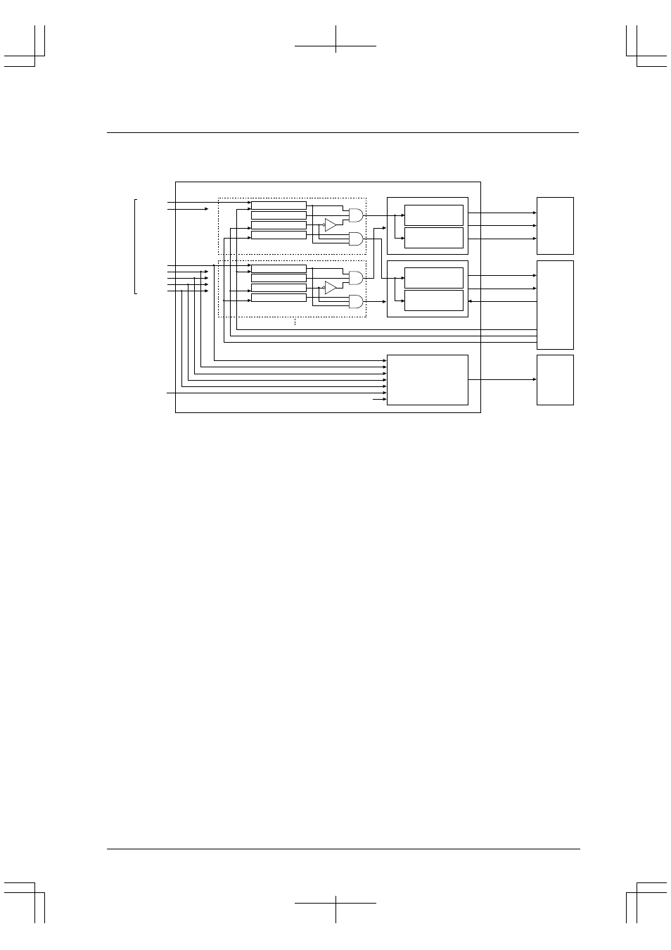
The interrupt controller is configured as shown in Figure 5.1.
CPU interrupt
priority judgment
(with interrupt level)
Interrupt vector
generator
Interrupt factor flag
Interrupt enable
IDMA request
IDMA enable
Interrupt request
Interrupt level
Interrupt vector
Key input x
HSDMA x
K5x (#DMAREQx) input
Software trigger
16-bit timer x
8-bit timer x
Serial I/F x
A/D
Port input x
CPU
ITC
IDMA request
priority judgment
(without interrupt level)
IDMA channel number
generator
Interrupt factor flag
Interrupt enable
IDMA request
IDMA enable
IDMA request
IDMA channel number
IDMA completion
Reset A
Reset B
Reset C
Ch.x HSDMA request
HSDMA trigger
selection circuit
IDMA
HSDMA
Ch.x
Interrupt
factors
Figure 5.1 Configuration of Interrupt Controller
The following sections explain the functions of the registers used to control interrupts.
Processor Status Register (PSR)
The PSR is a special register incorporated in the core CPU and contains control bits to enable or disable an interrupt
request to the CPU.
Interrupt Enable (IE) bit: PSR[4]
This bit is used to enable or disable an interrupt request to the CPU. When this bit is set to "1", the CPU is
enabled to accept a maskable interrupt request. When this bit is reset to "0", no maskable interrupt request is
accepted by the CPU.
When the CPU accepts an interrupt request (or some other trap occurs), it saves the PSR to the stack and resets
the IE bit to "0". Consequently, no maskable interrupt request occurring thereafter will be accepted unless the
IE bit is set to "1" in software program or the interrupt (trap) processing routine is terminated by the reti
instruction.
The IE bit is initialized to "0" (interrupts disabled) by an initial reset.
Interrupt Level (IL): PSR[11:8]
The IL bits disable the interrupts whose priorities are below the set interrupt level. For example, if the interrupt
level set in the IL is 3, the interrupts whose priorities are set below 3 in the interrupt priority register (described
later) are not accepted by the CPU even if the IE bit is set to "1". The IL and the interrupt priority register
together allow you to control the interrupt priorities in each interrupt system. For details about the interrupt
levels, refer to "Interrupt Priority Register and Interrupt Levels".
When the CPU accepts a maskable interrupt request, it saves the PSR to the stack and sets the IL to the
accepted interrupt's priority level. Therefore, even when the IE bit is set to "1" in the interrupt processing
routine, no interrupts whose priority levels are equal or below that of the interrupt currently being processed are
accepted unless the IL is rewritten.
The IL is restored to its previous status when the interrupt processing routine is terminated by the reti
instruction.