Iii-8 serial interface, Configuration of serial interfaces, Features of serial interfaces – Epson S1C33210 User Manual
Page 317
III PERIPHERAL BLOCK: SERIAL INTERFACE
S1C33210 FUNCTION PART
EPSON
B-III-8-1
III-8 SERIAL INTERFACE
Configuration of Serial Interfaces
Features of Serial Interfaces
The Peripheral Block contains four channels (Ch.0, Ch.1, Ch.2 and Ch.3) of serial interfaces, the features of which
are described below. The only differences between these four serial interfaces is that Ch. 1 and Ch. 3 support only
asynchronous operation.
• A clock-synchronized or asynchronous mode can be selected for the transfer method.
Clock-synchronized mode
Data length:
8 bits, fixed (No start, stop, and parity bits)
Receive error: An overrun error can been detected.
Asynchronous mode
Data length:
7 or 8 bits, selectable
Receive error: Overrun, framing, or parity errors can been detected.
Start bit:
1 bit, fixed
Stop bit:
1 or 2 bits, selectable
Parity bit:
Even, odd, or none; selectable
Since the transmit and receive units are independent, full-duplex communication is possible.
• Baud-rate setting: Any desired baud rate can be set by selecting the prescaler's division ratio, setting the 8-bit
programmable timer, or using external clock input (asynchronous mode only).
• The receive and transmit units are constructed with a double-buffer structure, allowing for successive receive and
transmit operations.
• Data transfers using IDMA or HSDMA are possible.
• Three types of interrupts (transmit data empty, receive data full, and receive error) can be generated.
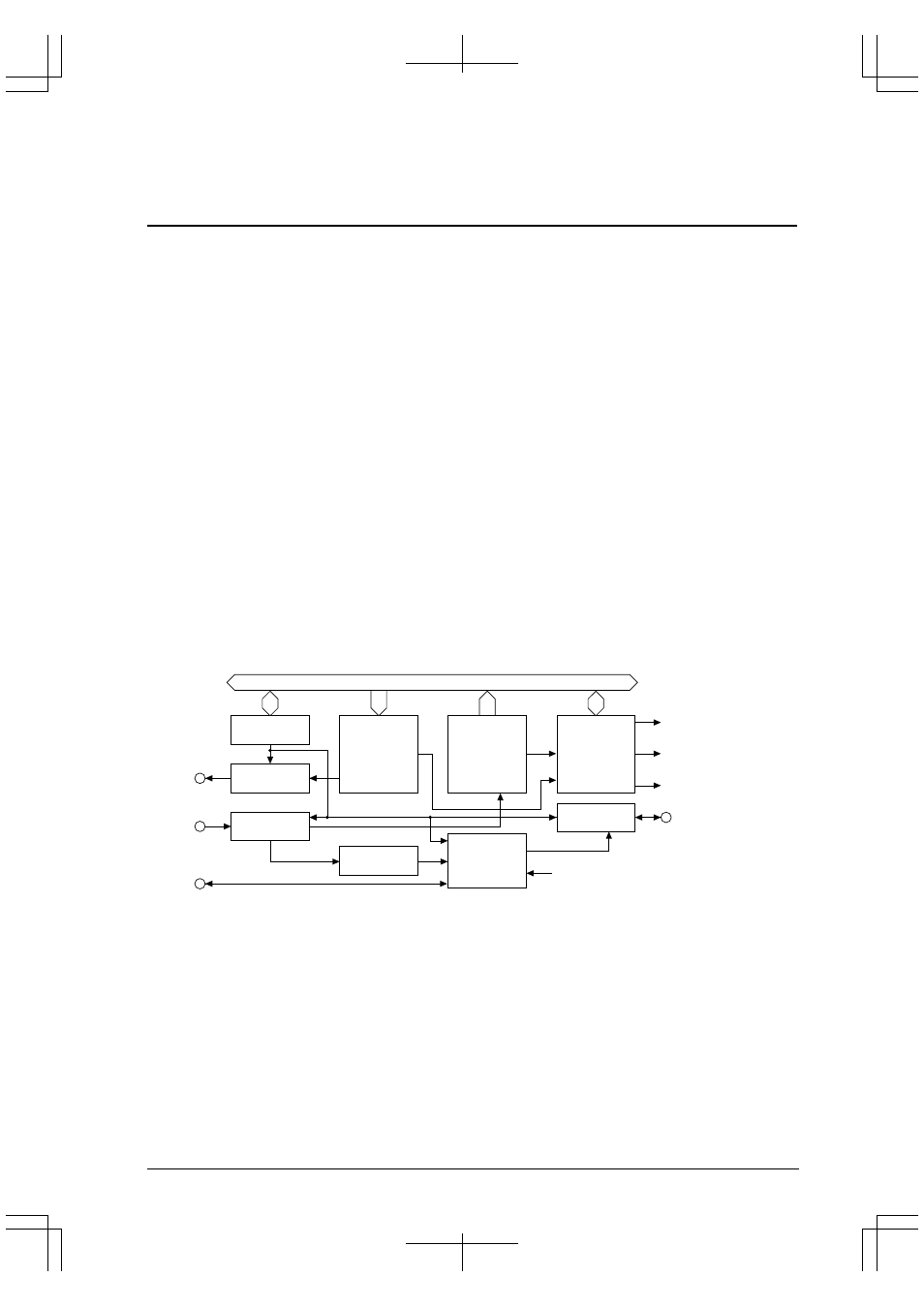
Figure 8.1 shows the configuration of the serial interface (one channel).
Control registers
Transmit unit
Data buffer
and
shift register
Interrupt
control circuit
Start bit
detection circuit
Clock
control circuit
Transmit data buffer empty
interrupt request
Receive data buffer full
interrupt request
Receive error
interrupt request
SOUTx
#SCLKx
#SRDYx
SINx
Internal data bus
Receive unit
Data buffer
and
shift register
Serial output
control circuit
Serial input
control circuit
Ready signal
control circuit
8-bit programmable timer output
Figure 8.1 Configuration of Serial Interface
Note: All interfaces have the same configuration and functionality except that Ch. 1 and Ch. 3 support
only asynchronous operation. The signal and control bit names are suffixed by a 0, 1, 2, or 3 to
indicate the channel number, enabling discrimination between channels 0 to 3. In this manual,
however, channel numbers 0 to 3 are replaced with "x" unless discrimination is necessary, because
explanations are common to all four channels.