Iii-9 input/output ports, Input ports (k ports), Structure of input port – Epson S1C33210 User Manual
Page 363
III PERIPHERAL BLOCK: INPUT/OUTPUT PORTS
S1C33210 FUNCTION PART
EPSON
B-III-9-1
III-9 INPUT/OUTPUT PORTS
The Peripheral Block has a total of 42 input/output ports. Although each pin is used for input/output from/to the
internal peripheral circuits, some pins can be used as general-purpose input/output ports unless they are used for the
peripheral circuits.
Input Ports (K Ports)
Structure of Input Port
The Peripheral Block contains 7 bits of input ports (K50 to K52, K60 to K63).
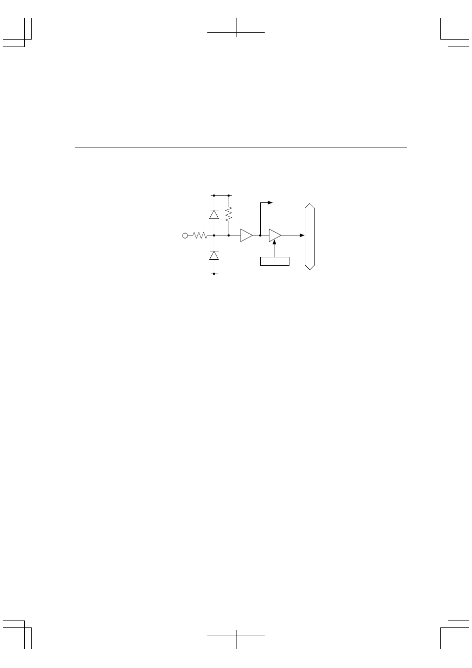
Figure 9.1 shows the structure of a typical input port.
Input interrupt
circuit
Kxx
KxxD
V
DD
*1
∗
2
∗
1
AV
DD
for K60–K63
∗
2
Available only for K50–K52
V
SS
Address
Internal data bus
Figure 9.1 Structure of Input Port
Each input-port pin is connected directly to the internal data bus via a three-state buffer. The state of the input signal
when read at an input port is directly taken into the internal circuit as data.
When K60 to K63 are used as general-purpose input ports, the power supply for the port input buffers is AV
DD
.
Therefore, when these ports are used as high-level or low-level input ports, the high level must be AV
DD
, and the low
level V
SS
.
If there is a potential difference between AV
DD
and V
DD
, in particular, if the level from outside is V
DD
, a current
may flow in the input buffer (when AV
DD
> V
DD
) or between V
DD
and AV
DD
(when AV
DD
< V
DD
). Therefore, if
these ports are not used, when the input level is fixed externally, it should be fixed at V
SS
or AV
DD
.