I/o pins of serial interface, Sinx (serial-data input pin), Soutx (serial-data output pin) – Epson S1C33210 User Manual
Page 318: Sclkx (clock input/output pin), Srdyx (ready-signal input/output pin)
III PERIPHERAL BLOCK: SERIAL INTERFACE
B-III-8-2
EPSON
S1C33210 FUNCTION PART
I/O Pins of Serial Interface
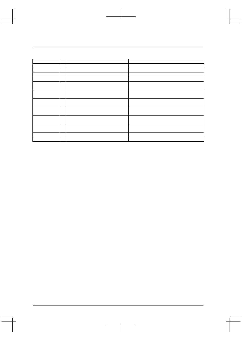
Table 8.1 lists the I/O pins used by the serial interface.
Table 8.1 Serial-Interface Pin Configuration
Pin name
I/O
Function
Function select bit
P00/SIN0
I/O I/O port / Serial IF Ch.0 data input
CFP00(D0)/P0 function select register(0x402D0)
P01/SOUT0
I/O I/O port / Serial IF Ch.0 data output
CFP01(D1)/P0 function select register(0x402D0)
P02/#SCLK0
I/O I/O port / Serial IF Ch.0 clock input/output
CFP02(D2)/P0 function select register(0x402D0)
P03/#SRDY0
I/O I/O port / Serial IF Ch.0 ready input/output
CFP03(D3)/P0 function select register(0x402D0)
P04/SIN1/
#DMAACK2
I/O I/O port / Serial IF Ch.1 data input
/ #DMAACK2 signal output
CFP04(D4)/P0 function select register(0x402D0)
CFEX4(D4)/Port function extension register(0x402DF)
P05/SOUT1/
#DMAEND2
I/O I/O port / Serial IF Ch.1 data output
/ #DMAEND2 signal output
CFP05(D5)/P0 function select register(0x402D0)
CFEX5(D5)/Port function extension register(0x402DF)
P27/TM5/SIN2
I/O I/O port / Serial IF Ch.2 data input
CFP27(D[7:0])/Function select register(0x402D8)
SSIN2(D[0:1])/Function select register(0x402DB)
P26/TM4/SOUT2
I/O I/O port / Serial IF Ch.2 data output
CFP26(D[6:0])/Function select register(0x402D8)
SSOUT2(D[1:1])/Function select register(0x402DB)
P25/TM3/#SCLK2
I/O I/O port / Serial IF Ch.2 serial clock input/output CFP25(D[5:0])/Function select register(0x402D8)
SSCLK2(D[2:1])/Function select register(0x402DB)
P24/TM2/#SRDI2
I/O I/O port / Serial IF Ch.2 ready input/output
CFP24(D[4:0])/Function select register(0x402D8)
SSTDY2(D[3:1])/Function select register(0x402DB)
TXD
I/O Serial IF Ch.3 data output (SOUT3)
When MSEL pin input is at Low level
RXD
I/O Serial IF Ch.3 data input (SIN3)
When MSEL pin input is at Low level
SINx (serial-data input pin)
This pin is used to input serial data to the device, regardless of the transfer mode.
SOUTx (serial-data output pin)
This pin is used to output serial data from the device, regardless of the transfer mode.
#SCLKx (clock input/output pin)
This pin is used to input or output a clock.
In the clock-synchronized slave mode, it is used as a clock input pin; in the clock-synchronized master mode, it
is used as a clock output pin.
In the asynchronous mode, this pin is used as clock input when an external clock is used. This pin is not used
when the internal clock is used, so it can be used as an I/O port.
#SRDYx (ready-signal input/output pin)
This pin is used to input or output the ready signal that is used in the clock-synchronized mode.
In the clock-synchronized slave mode, it is used as a ready-signal output pin; in the clock-synchronized master
mode, it is used as a ready-signal input pin.
This pin is not used in the asynchronous mode, so it can be used as an I/O port.