Irda interface, Outline of irda interface, Setting irda interface – Epson S1C33210 User Manual
Page 337
III PERIPHERAL BLOCK: SERIAL INTERFACE
S1C33210 FUNCTION PART
EPSON
B-III-8-21
IrDA Interface
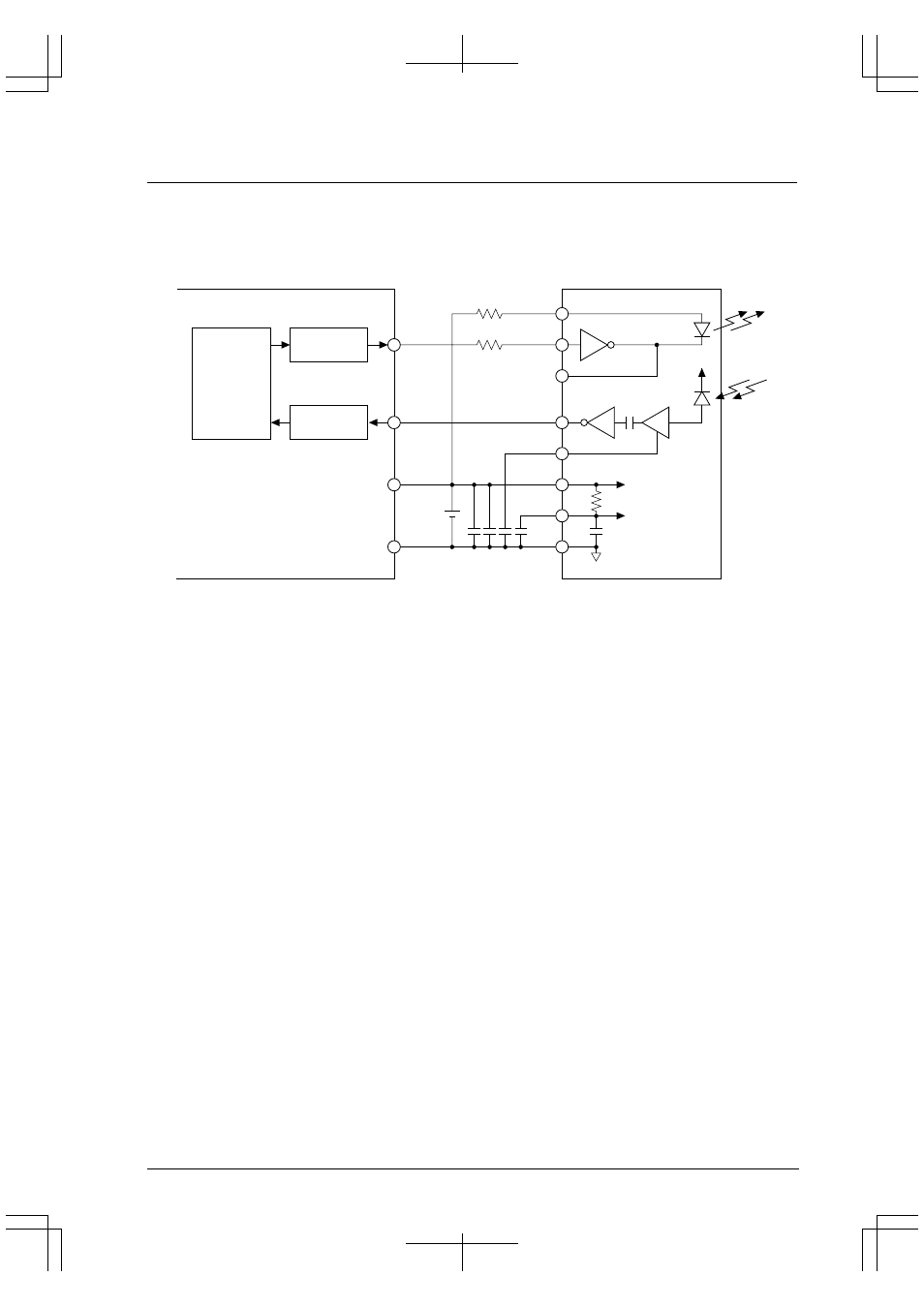
Outline of IrDA Interface
Each channel of the serial interface contains a PPM modulator circuit, allowing an infrared-ray communication
circuit to be configured based on IrDA 1.0 simply by adding a simple external circuit.
PPM
Modulator
SOUTx
LED
TXD
LED A
LED C
RXD
CX1
Vcc
CX2
GND
V
P1N
V
P1N
Photodiode
SINx
V
DD
V
SS
Serial I/F
PPM
Modulator
S1C33
Infrared communication module
(Example: HP HSDL-1000)
Figure 8.14 Configuration Example of IrDA Interface
This IrDA interface function can be used only when the selected transfer mode is an asynchronous mode.
Since the contents of the asynchronous mode are applied directly for the serial-interface functions other than the
IrDA interface unit, refer to "Asynchronous Interface", for details on how to set and control the data formats and data
transfers.
Setting IrDA Interface
When performing infrared-ray communication, the following settings must be made before communication can be
started:
1. Setting input/output pins
2. Selecting the interface mode (IrDA interface function)
3. Setting the transfer mode
4. Setting the input clock
5. Setting the data format
6. Setting the interrupt/IDMA/HSDMA
7. Setting the input/output logic
The contents for items 1 through 5 have been explained in connection with the asynchronous interface. For details,
refer to "Asynchronous Interface". For details on item 6, refer to "Serial Interface Interrupts and DMA".
Note: Before making these settings, always make sure the serial interface is inactive (TXENx and RXENx
are both set to "0"), as a change in settings during operation could cause a malfunction.
In addition, be sure to set the transfer mode in (3) and the following items before selecting the IrDA
interface function in (2).