3 plc i/o expansion board pl 410 b – HEIDENHAIN TNC 306 Technical Manual User Manual
Page 69
3–54
TNC 416/TNC 406/TNC 306
PLC inputs/outputs
3/99
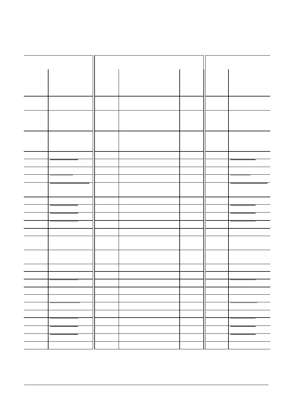
11.3 PLC I/O expansion board PL 410 B
One PL 410 B board with 64 PLC inputs, 31 PLC outputs and the "Control is operational" output can
be connected to the logic unit. The PL 410 B can be mounted directly on the logic unit. See section
"Power supply" for the power connection.
LE416/LE 406 connector X47
LE 306 connector X26
Connecting cable Id. Nr. 289 111 ..
1st PL 410 B
X47 D-sub
terminal
(male)
25-pin
Assignment
D-sub
connector
(female)
25-pin
D-sub
connector
(male)
25-pin
X1 D-sub
terminal
(female)
25-pin
Assignment
1
0 V
1
Brown, Yellow, Pink, Red,
Violet
1
1
0 V
2
0 V
2
Red/Blue, Brown/Green,
Yellow/Brown, Gray/Brown,
Pink/Brown
2
2
0 V
3
0 V
3
Brown/Blue, Brown/Red,
Brown /Black, Yellow/Gray,
Yellow/Pink
3
3
0 V
4
Do not use
4
Gray/Green
4
4
Serial IN 2
5
Address 6
5
White/Green
5
5
Address 6
6
INTERRUPT
6
Pink/Green
6
6
INTERRUPT
7
RESET
7
Green/Blue
7
7
RESET
8
WRITE EXTERNAL
8
White/Blue
8
8
WRITE
EXTERNAL
9
WRITE EXTERNAL
9
White/Red
9
9
WRITE EXTERNAL
10
Address 5
10
Gray/Pink
10
10
Address 5
11
Address 3
11
Blue
11
11
Address 3
12
Address 1
12
Green
12
12
Address 1
13
Do not use
13
13
13
Do not use
14
PCB identifier 4
14
Yellow/Blue, Pink/Blue,
Yellow/Black
14
14
+ 12 V
15
PCB identifier 3
15
Yellow/Red, Gray/Red,
Pink/Red
15
15
+ 12 V
16
Do not use
16
Gray/Blue
16
16
PCB identifier 2
17
Do not use
17
Green/Black
17
17
PCB identifier 1
18
Address 7
18
White/Yellow
18
18
Address 7
19
Serial IN 1
19
White/Black
19
19
Serial IN 1
20
EMERGENCY STOP
20
Green/Red
20
20
EMERGENCY STOP
21
Serial OUT
21
White/Gray
21
21
Serial OUT
22
Serial OUT
22
White/Pink
22
22
Serial OUT
23
Address 4
23
Black
23
23
Address 4
24
Address 2
24
Gray
24
24
Address 2
25
Address 0
25
White
25
25
Address 0
Housing
External shield
Housing
External shield
Housing
Housing
External shield