HEIDENHAIN TNC 306 Technical Manual User Manual
Page 120
4-20
TNC 406/TNC 306
1 Machine axes
3/97
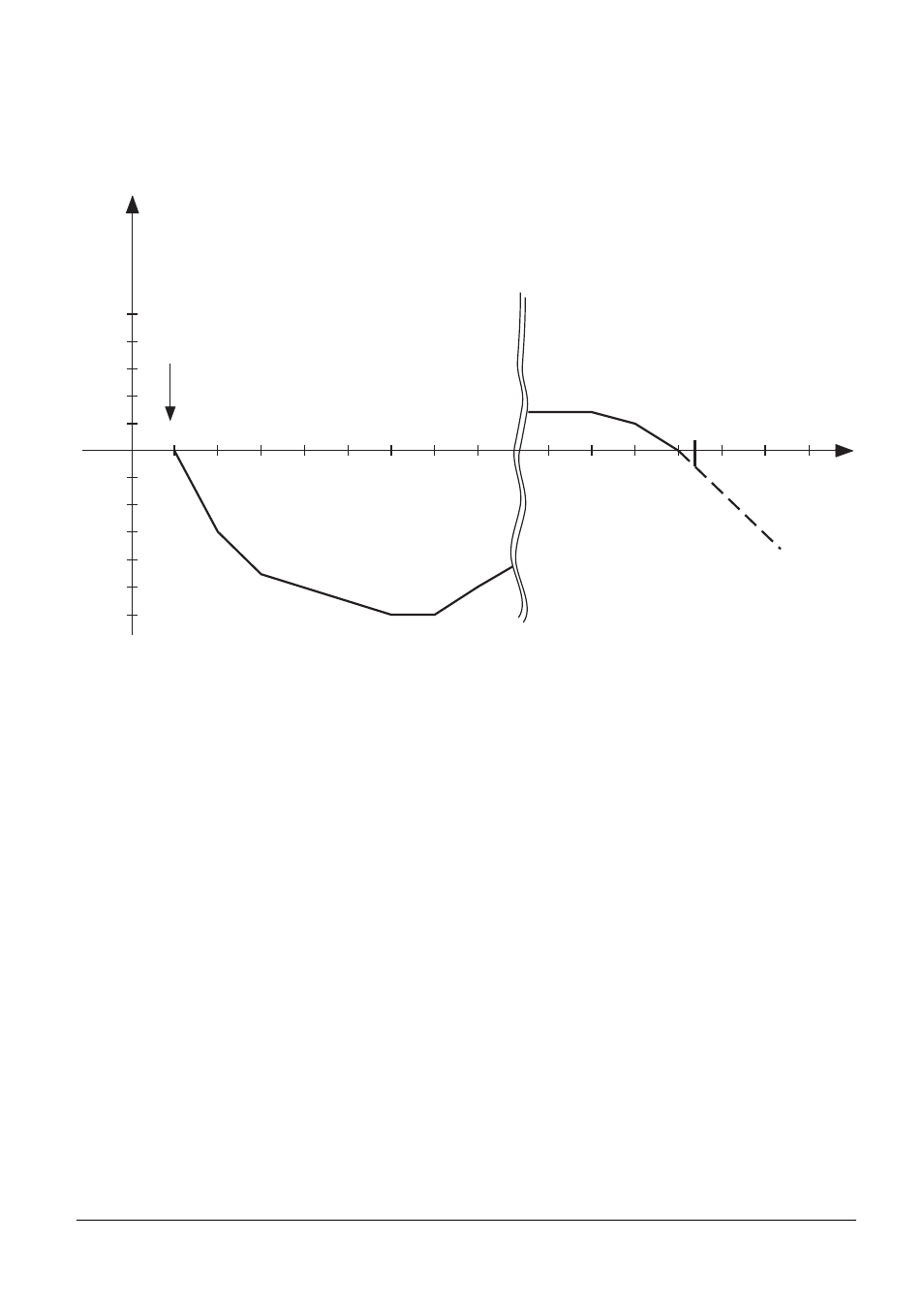
Example:
Y = F(Z)
Measurement length on Z axis = 1 000 mm
Desired distance between correction points = 1 000 mm : 64 = 15.62 mm
Possible exponent (base 2) = 2
14
= 16.384 mm
Datum point: –990
–957.232
–891.696
–908.08
Error in Y
[mm]
Z
[mm]
0.1
0.08
0.06
0.04
0.02
-0.1
-0.08
-0.06
-0.04
-0.02
–990
–973.616
–940.848
–924.464
–875.312
-0.12
–56.112
–39.728
–23.344
–6,96
+9.424
+25.808
Machine
datum
Datum
0
The errors which have thus been determined can be entered in the form of a table directly into the
control unit. However, axis error compensation is only effective when it is enabled for a specific axis
by the machine parameter MP730.
Before entering the correction table the code number 105 296 must be entered and the function
"COMPENSATION VALUE LIST" must be selected. The control will initially show the correction table
for the X axis, whereby "SETUP" is the interval between correction points:
X = F(X)
DATUM POINT +0.000
SETUP 1
0 X+0.000 X+0.000
1 X+0.001 X+0.000
2 X+0.002 X+0.000
.
.
.
The orange axis key can be used to select a different fault-causing axis for the X axis. After pressing
the GOTO key, the axis keys can be used to select a correction table for one of the other axes. The
correction value which is entered may not exceed the maximum correction-value difference.