Connection diagram, 1 connection diagram – HEIDENHAIN TNC 306 Technical Manual User Manual
Page 172
4-72
TNC 406/TNC 306
5 EMERGENCY STOP routine
3/97
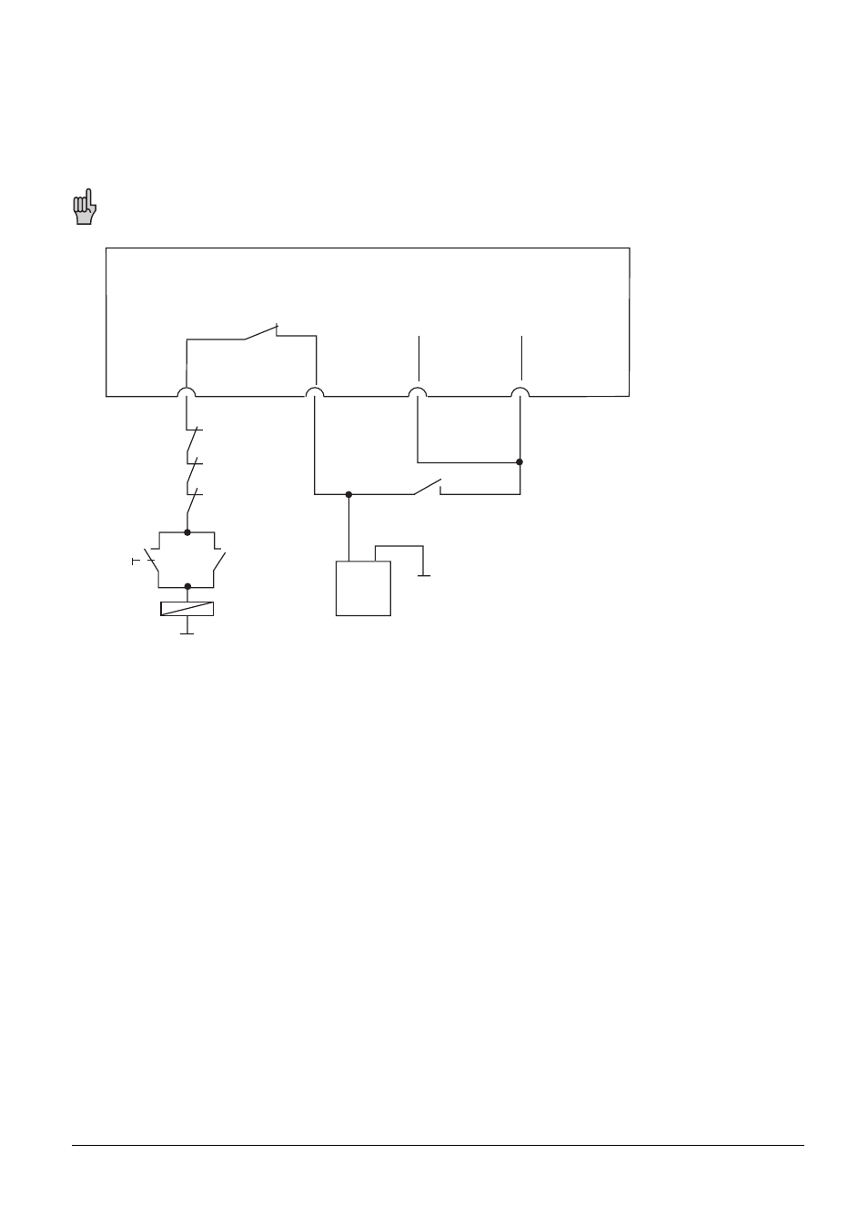
5.1 Connection diagram
Under fault conditions, the "control operational" output should switch off the 24-volt supply. Because
of the enormous importance of this function this output is tested by the control every time the
power is switched on.
This diagram represents a proposal for circuitry. The machine tool builder is responsible for
complying with applicable safety regulations.
+ -
Logic unit
Switch opens briefly when the control voltage
of each microprocessor is switched on
X41/34 X44/2 X44/1 X42/4
X21/34 X24/2 X24/1 X22/4
"Control is
ready"
24V not
interruptible
24V
interruptible
"Control ready"
feedback
EMERGENCY
STOP
buttons
Control
voltage
on
k1
k1
K1
24 V
PLC
LE406
LE360
This manual is related to the following products: