2 plc program example – HEIDENHAIN TNC 306 Technical Manual User Manual
Page 228
4-128
TNC 406/TNC 306
14 Electrode changer
2/97
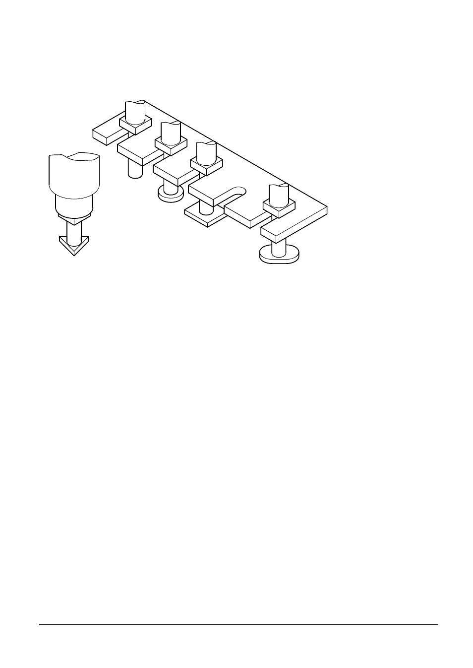
14.2 PLC program example
The following description covers a five station pick-and-place electrode changer with corresponding
flowcharts and PLC functions. Before production of a PLC program the outline structure for the
program run must be taken into consideration (sequencing, interlocks, buffer marks etc.)
Each electrode change should be commenced with a TOOL CALL command. The TOOL DEF
command has no function within the PLC. In this example each rack position in the electrode
changer is defined by two machine parameters (X coordinate and Y coordinate). In the following flow
charts variable names are used to aid understanding of the logic. In the PLC program these variable
names would be replaced by the word addresses.
In program run a TOOL CALL block is executed by the NC in accordance with the value in machine
parameter MP7480.0. If MP7480.0 = 1, the NC only loads the new tool number into the PLC word
W262 if it is different from the current tool number. If MP7480.0 = 2, PLC word W262 is loaded with
the new tool number at every TOOL CALL. When a value is loaded into W262, the NC sets strobe
marker M2046 to inform the PLC program which should then take appropriate action, i.e. change the
electrode. With the change sequence completed the PLC program should set marker M2483 to
indicate to the NC the end of the TOOL CALL block thus allowing the NC run to continue.
MP7480.0
Output of Tool Number
0 = No output
1 = Output only when tool number changes
2 = Output with every TOOL CALL
(See Chapter 5, "Machine Parameter List")
W262
Tool Number (if MP7480.0 = 1 or 2)