HEIDENHAIN TNC 306 Technical Manual User Manual
Page 30
3/99
TNC 416/TNC 406/TNC 306
Overview of connections
3–15
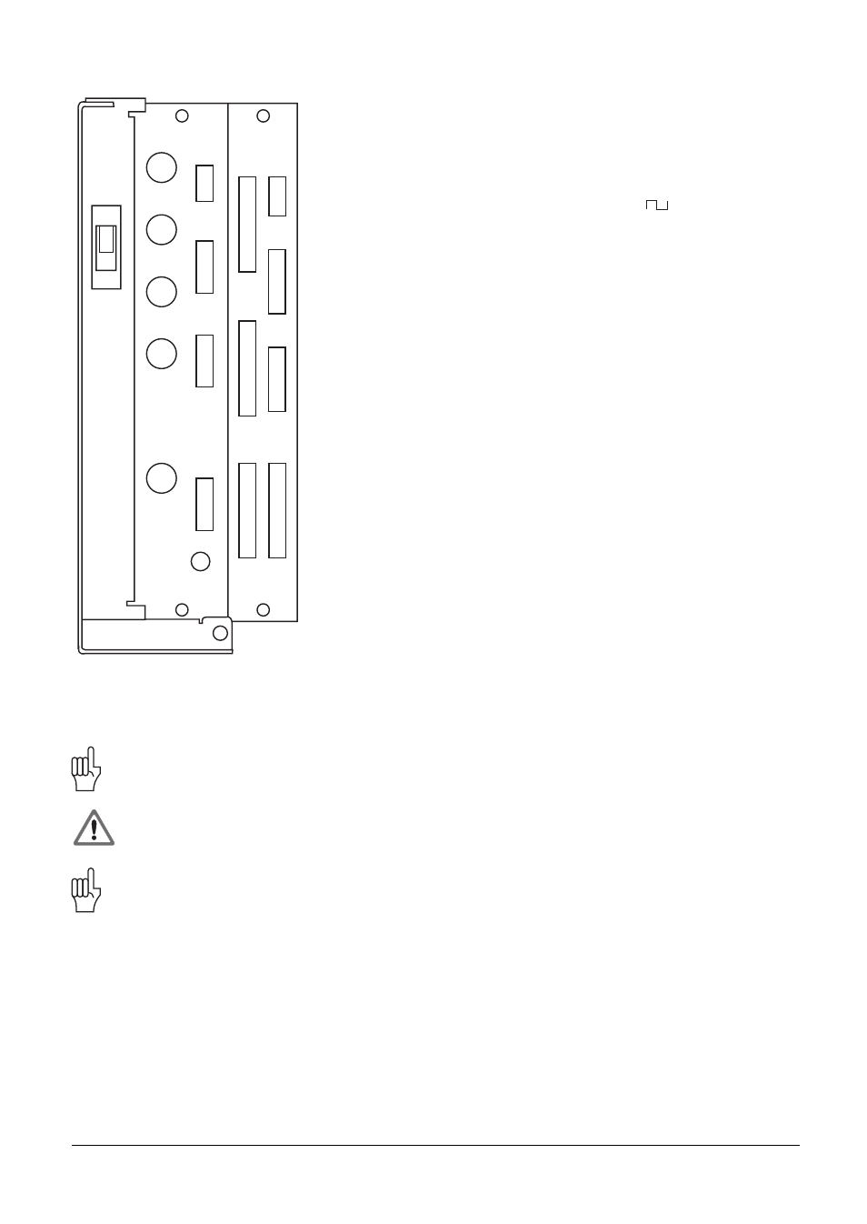
LE 306
X1
X2
X3
X4
X6
X11
X12
X8
B
X24
24V
X31
X9
X21
X22
X23 X27
X26
X25
X1
Measuring system 1 (11µA)
X2
Measuring system 2 (11µA)
X3
Measuring system 3 (11µA)
X4
Measuring system 4 (11µA)
X6
Measuring system (
)
X8
Nominal value outputs 1,2,3,4;
gap signal input
X9
VDU BE212/BF110
X11
Electronic handwheel HR 130/HR 410
X12
Touch probe system
Short-circuit signal input
X21
PLC output
X22
PLC input
X23
TNC keyboard TE355
X25
Data interface RS-232-C/V.24
X26
PLC I/O board PL 410 B
X27
Machine operating panel
X31
Power supply 24 V for NC
X24
Power supply 24 V for PLC
B Signal ground
Interfaces X1, X2, X3, X4, X6, X8, X9, X11, X12, X21, X22, X23, X25, X26, and X27 comply
with the recommendations in VDE 0160, 5. 88 for separation from line power.
Danger to internal components!
Do not engage or disengage any connections while the unit is under power.
The outputs at connection X.... (indicate pin number if appropriate) are metallically isolated
from the device electronics by means of optocouplers.