Plc power supply, 2 plc power supply – HEIDENHAIN TNC 306 Technical Manual User Manual
Page 34
3/99
TNC 416/TNC 406/TNC 306
Power supply
3–19
4.1.2 PLC power supply
Power supply for the PLC on board
LE 416/LE 406
X44
LE 306
X24
Pin number
Assignment
1
+ 24 V DC, switched off by EMERGENCY STOP
2
+ 24 V DC, not switched off by EMERGENCY STOP
3
0 V
Power supply for the PL 410 B
The PLC outputs are powered in groups.
Terminal
Assignment
PLC output
X9
0V
X10
+24 V power for logic and for "Control is operational"
X11
+24 V power for outputs
O32 to O39
X12
+24 V power for outputs
O40 to O47
X13
+24 V power for outputs
O48 to O55
X14
+24 V power for outputs
O56 to O62
The PLC inputs and outputs on the LE and PL 410 B are powered by the 24 V machine control voltage
supply.
Danger to internal components!
Voltage sources for external circuitry must conform to the recommendations in VDE
0160, 5. 88 for low-voltage electrical separation.
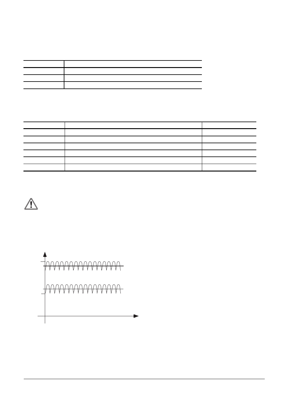
Superimposed AC components, such as those caused by a three-phase bridge rectifier without smoothing,
are permissible up to a ripple factor of 5% (see DIN 40110/10.75, Section 1.2). This means an absolute
upper voltage limit of 32.6 V and an absolute lower voltage limit of 18.5 V:
32.6 V
31 V
20.4 V
18.5 V
U
t
The 0 V line of the PLC power supply must be grounded with a ground lead (ø 6 mm2) to the main
signal ground of the machine.