Connector assignment, 1 connector assignment – HEIDENHAIN TNC 306 Technical Manual User Manual
Page 49
3–34
TNC 416/TNC 406/TNC 306
Nominal value output / Gap signal input 3/99
6.1 Connector assignment
X8 nominal value output/Gap signal input
D-sub connector (15-pin female insert)
X8 Nominal Value Output
Logic unit
Connecting Cable
D-sub terminal
(female) 15-pin
Assignment
D-sub
connector
(male) 15-pin
Color
1
Nominal value output 1
1
BN
2
Analog input, gap signal
2
BN/GN
3
Nominal value output 2
3
YL
4
Nominal value output 5
4
RD/BL
5
Nominal value output 3
5
PK
6
0V Nominal value output 5
6
GY/PK
7
Nominal value output 4
7
RD
8
Nominal value output 6
8
VI
9
0V Nominal value output 1
9
WH
10
0V Analog input
10
WH/GY
11
0V Nominal value output 2
11
GN
12
Not used
12
13
0V Nominal value output 3
13
GY
14
0V Nominal value output 4
14
BL
15
0V Nominal value output 6
15
BK
Housing
External shield
Housing
External shield
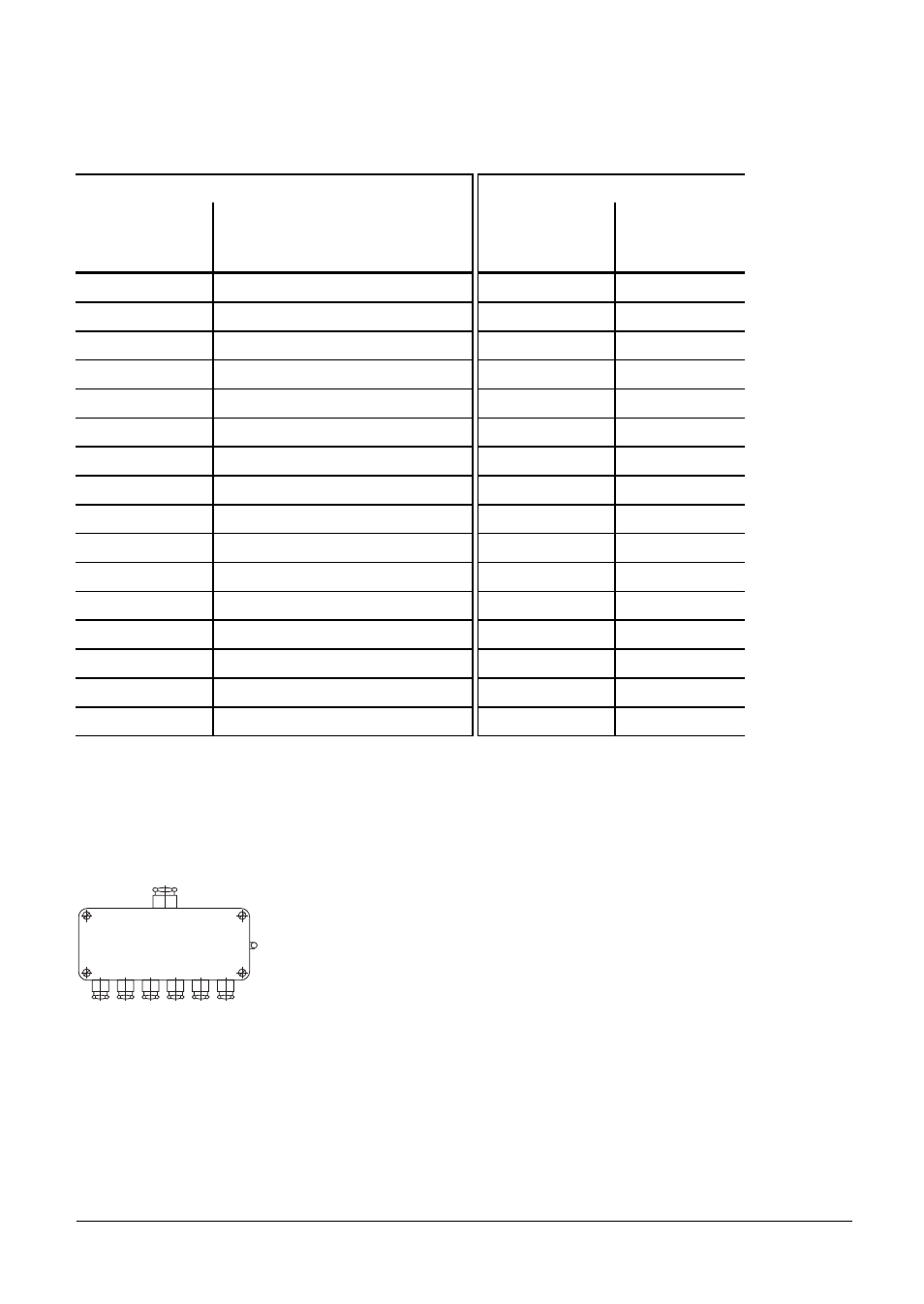
No more than one intermediate terminal clamp is allowed on the connecting cable to the nominal
value outputs. The clamp must be made in a grounded connection box. This is necessary when the
cable must branch to physically separate servo inputs. It is only possible to ground the shielding of
the servo leads in this way. If required, suitable connection boxes are available from HEIDENHAIN
with the Id.-Nr. 251 249 01.
Connection box
The casing of the connection box must be electrically connected with the frame of the machine.
The 0 V of the nominal value differential input must be joined to signal ground, (cable cross-section
Ø 6 mm², see also under "Grounding plan").