Micrologix follower, Control connections, Configuring the ultra1500 – Rockwell Automation 2092-DAx Ultra1500 User Manual User Manual
Page 91: Micrologix follower -11
Publication 2092-UM001D-EN-P — July 2005
Ultra1500 Application Examples
5-11
MicroLogix Follower
The Ultra1500 can be integrated into a MicroLogix PLC system as a
positioning drive. The following MicroLogix devices offer pulse train output
(PTO) capability:
In this configuration, the Ultra1500 drive is operated in Follower mode, and
the controller provides step and direction commands to the drive.
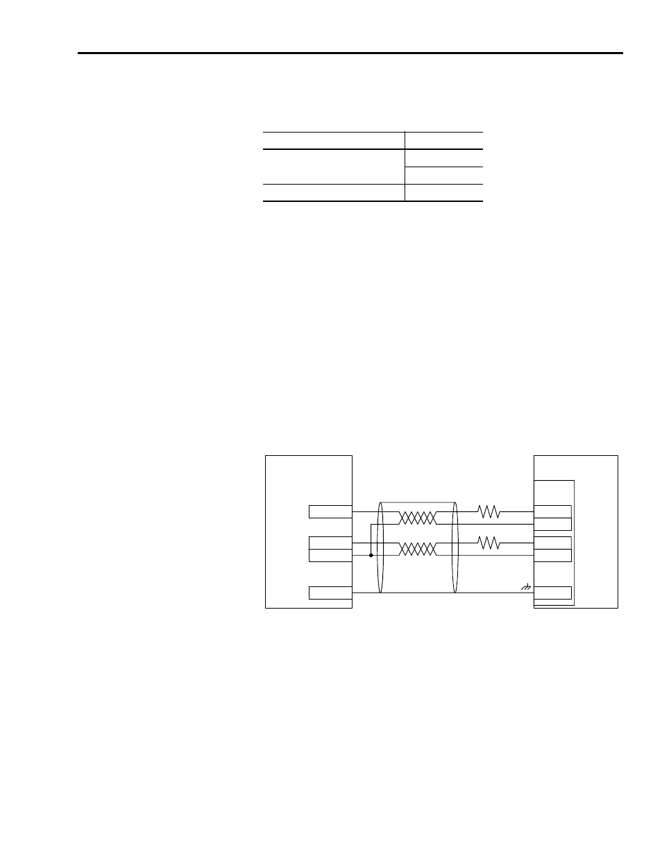
Control Connections
Figure 5.3 shows the recommended connections for a typical system using a
MicroLogix controller with the Ultra1500. The 2.2k
Ω resistor is necessary in
order to limit the current through the opto-isolator input of the Ultra1500,
since the Ultra1500 AX and BX inputs are designed for 5V interfaces, and the
MicroLogix outputs have 24V levels.
Figure 5.3
Ultra1500 to MicroLogix Control Wiring Example
Configuring the Ultra1500
The Setup Wizard in Ultraware provides a quick method to configure the
Ultra1500 for use with a MicroLogix controller in follower mode. Refer
to Configuring the Ultra1500 on page 5-3 for setup details.
The Ultraware Setup Wizard will prompt for a Gear Ratio setting. The Gear
Ratio parameter will determine how many motor encoder counts will result
from each command count from the controller. Since the frequency of the
Programmable Logic Controller
Catalog Number
MicroLogix 1200
1762-L24BXB
1762-L40BXB
MicroLogix 1500
1764-28BXB
MICROLOGIX
PLC
OUT2
ULTRA1500
AX+
AX-
11
12
CHASSIS
SHIELD
CN1
OUT3
COM
BX+
BX-
13
14
2.2k
Ω
2.2k
Ω