Rockwell Automation 2092-DAx Ultra1500 User Manual User Manual
Page 43
Publication 2092-UM001D-EN-P — July 2005
Ultra1500 Connector Data
2-13
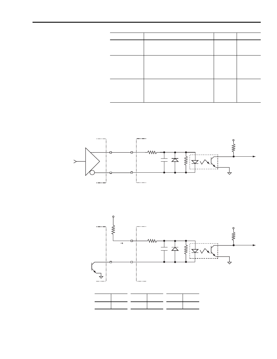
Figure 2.3 depicts common interface types for Ultra1500 Position Commands.
Figure 2.10
Position Command Interface Examples
OFF State Input
Voltage
Input voltage difference between the + input
and the - input that is detected as an OFF
state.
1V
-3V
Signal Frequency
(open collector input
drive)
Input frequency of the AX or BX inputs. Count
frequency is four times this frequency for A/B
type inputs, and equal to this frequency for
Step/Direction and Step Up/Step Down
inputs.
—
250 kHz
Signal Frequency
(differential driver
input drive)
Input frequency of the AX or BX inputs. Count
frequency is four times this frequency for A/B
type inputs, and equal to this frequency for
Step/Direction and Step Up/Step Down
inputs.
—
900 kHz
Parameter
Description (Continued)
Minimum
Maximum
+5V
AX-
680
Ω
Logic Ground
M456
1 k
Ω
0.001
µF
150
Ω
AX+
+
-
VIN
+5V
AX-
680
Ω
Logic Ground
M456
1 k
Ω
0.001
µF
150
Ω
AX+
V
CC
R1
I
IN
Line Driver Interface
Open Collector Interface
Controller
Ultra1500
Drive
V
IN
must be between 2.8V and 3.7V for an ON state to be recognized.
Controller
Ultra1500
Drive
R
1
must be chosen so that the input current, I
IN
, is between 7mA and 15mA for an ON state to be recognized:
V
CC
R
1
V
CC
R
1
V
CC
R
1
5V
180
Ω 12V
1
k
Ω 24V
2.2
k
Ω