Analog velocity mode, Analog velocity mode -42, Figure 5.22 analog velocity mode block diagram – Rockwell Automation 2092-DAx Ultra1500 User Manual User Manual
Page 122
Publication 2092-UM001D-EN-P — July 2005
5-42
Ultra1500 Application Examples
The velocity command limit is set to the minimum of the following:
• Zero if the velocity command is in the direction of an active overtravel
limit,
• Manual Velocity Limit (if activated),
• Analog Velocity Limit (if activated), and
• Motor rated speed.
The current command limit is set to the minimum of the following:
• Positive / Negative Internal Current Limit,
• Positive / Negative External Current Limit,
• Stopping Current (if activated), and
• Drive Peak / Motor Peak Current Rating.
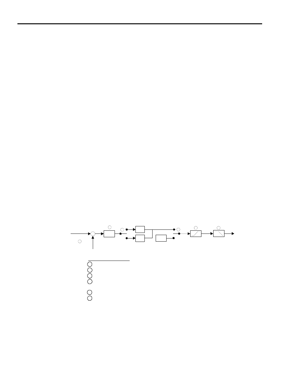
Analog Velocity Mode
Figure 5.22 shows the block diagram of the analog velocity mode for the
Ultra1500:
Figure 5.22
Analog Velocity Mode Block Diagram
Block/Switch definitions shown in Figure 5.22 refer to the Ultraware parameter names where applicable.
+
+
4
A nalog Velocity
Command (Volts)
K
v
Analog Vel ocity
Comma nd
O ffset (Volts)
0.0
Velo city
Command
To Velocity
Regulator
Accel
L imits
Ve loci ty
Comma nd
Filte r
2
5
6
Block/Switch Definitions
1
Mode Configuration : Analog : Velocity Comm and Offset
2
Mode Configuration : Analog : Velocity Scale
3
Main Drive Window : Command Polarity
4
Main Drive Window : Speed Functions : Zero Clamp
Digital Inputs : Zero Speed Clamp Enable
5
Main Drive Window : Accleration Limits
6
Tuning : Main Velocity Regulator Gains : Low Pass Filter Bandwidth
3
1
-1
1