Cable categories for the ultra1500, Mounting guidelines to reduce electrical noise, Ac line filters – Rockwell Automation 2092-DAx Ultra1500 User Manual User Manual
Page 27: Ac line filters -15
Publication 2092-UM001D-EN-P — July 2005
Installing Your Ultra1500
1-15
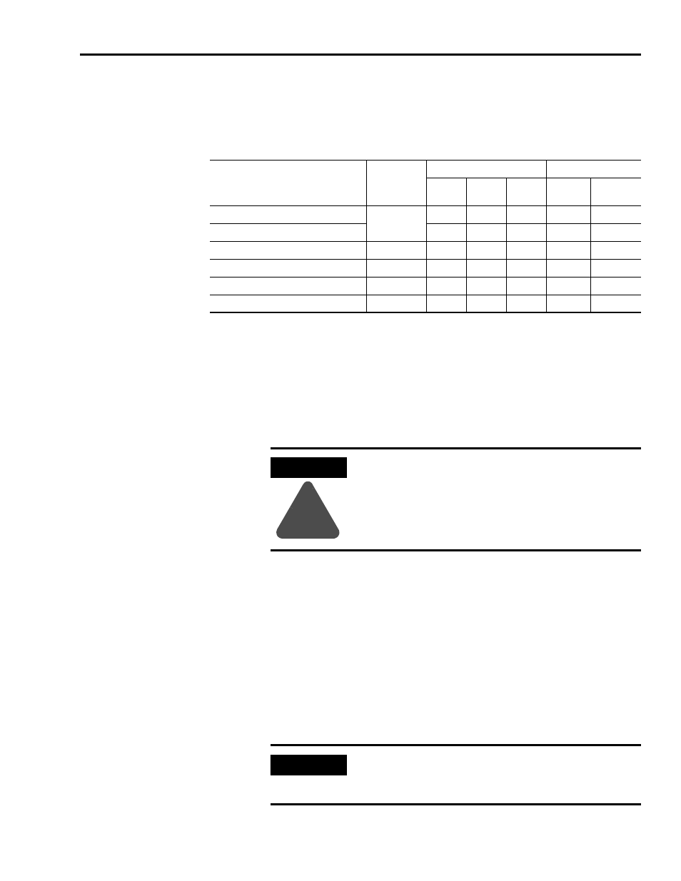
Cable Categories for the Ultra1500
The table below indicates the zoning requirements of cables connecting to the
Ultra1500.
Mounting Guidelines to Reduce Electrical Noise
When mounting an AC line (EMC) filter refer to the sections below for
guidelines designed to reduce system failures caused by excessive electrical
noise.
AC Line Filters
Observe the following guidelines when mounting your AC line (EMC) filter
(refer to Figure 1.5 for an example).
• Mount the AC line filter and bonded cabinet ground bus on the same
panel as the Ultra1500, and as close to the Ultra1500 as possible.
• Good HF bonding to the panel is critical. For painted panels, refer to
• Segregate input and output wiring as far as possible.
Wire/Cable
Connector
Zone
Method
Very
Dirty
Dirty
Clean
Ferrite
Sleeve
Shielded
Cable
L1, L2, L3 (shielded cable)
Input Power
X
X
L1, L2, L3 (unshielded cable)
X
U, V, W (motor power)
Output Power
X
X
24V Wiring
CN1
X
Motor Feedback
CN2
X
X
Serial Communications
CN3
X
X
ATTENTION
!
High voltage exists in AC line filters. The filter must be
grounded properly before applying power. Filter capacitors
retain high voltages after power removal. Before handling
the equipment, voltages should be measured to determine
safe levels. Failure to observe this precaution could result in
personal injury.
IMPORTANT
CE test certification applies only to AC line filter and single
drive. Multiple drive loads may perform satisfactorily, but
the user takes legal responsibility.