Set parameter mode – Rockwell Automation 2092-DAx Ultra1500 User Manual User Manual
Page 172
Publication 2092-UM001D-EN-P — July 2005
D-8
Ultra1500 Operator Interface
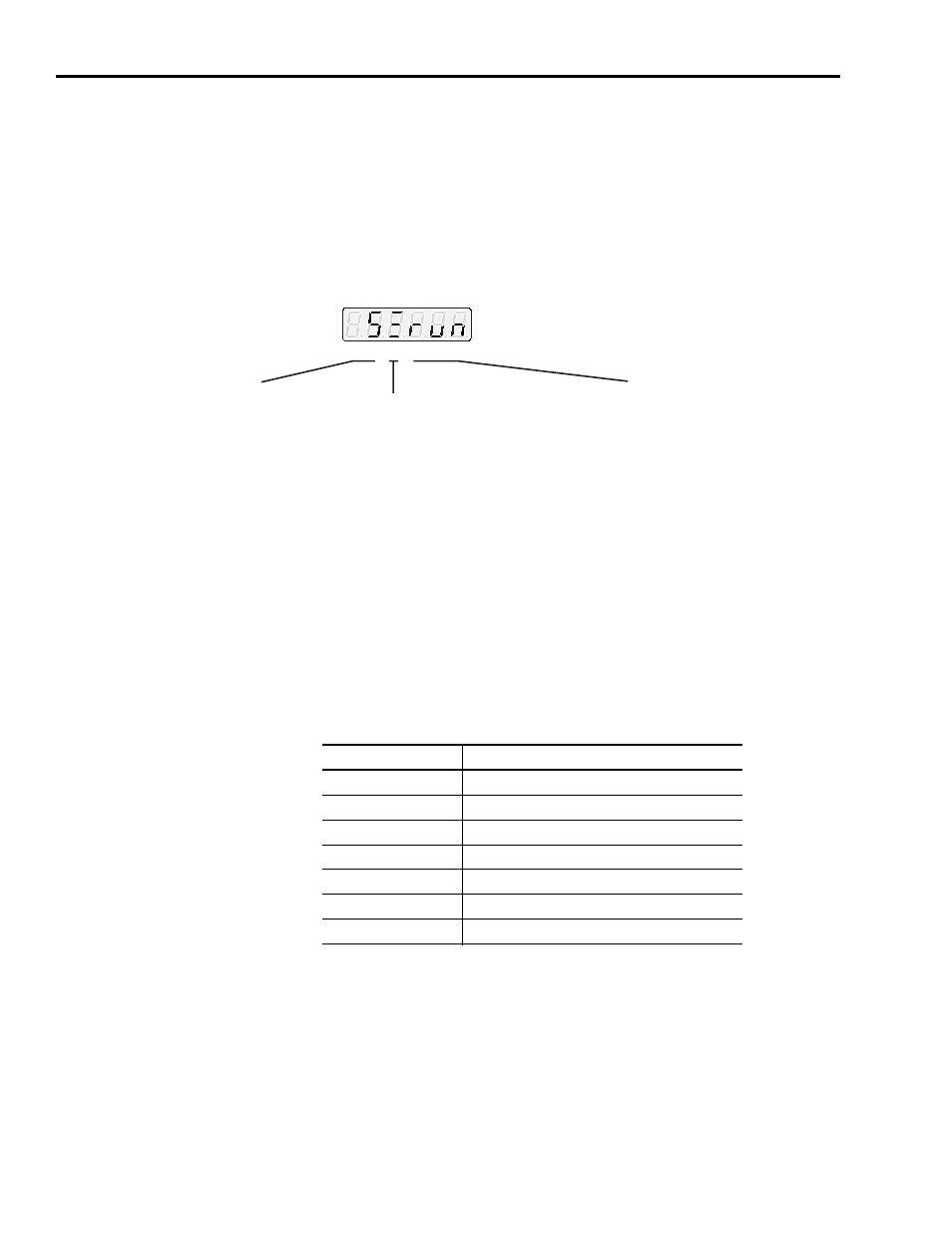
Figure D.2 shows these categories and briefly defines the information
provided by each category.
Refer to Maintaining and Troubleshooting Your Ultra1500 beginning on page 6-1
for a complete listing and description of Warning Messages, Error Displays,
and Overtravel Conditions.
Figure D.2
Operational Drive Displays
Set Parameter Mode
The Set Parameter mode allows adjustments to the parameters that control
drive operation. Parameters are grouped into the following categories:
To display parameter settings:
1. Enter the Set Parameter mode by pressing the MODE key.
The text message Pr-x.xx indicates the Set Parameter mode is active.
2. After you select a parameter, the active digit flashes.
The UP or DOWN key increments or decrements the parameter number.
The LEFT and RIGHT key moves the active digit within the parameter.
Character: 0 1 2 3 4 5
rdY = Drive is disabled, but ready to be enabled
run = Drive is enabled and motor is under control
Status: Characters 3 through 5
Middle Row = Active if velocity exceeds Up To Speed parameter
Row Display: Character 2
Top Row = Inactive for any Current mode
Active if Velocity Mode. and Velocity Error is within the velocity window
Active if Follower Mode. and Position Error is within following error setting
Bottom Row = Active for hall startup motors once the commutation angle is set
Active for TL-Series motor once the first index pulse occurs
C = Analog Current
d = Dual Current Command
Control Mode: Characters 0 and 1
F = Follower
S = Analog Speed
P = Preset Velocity
Parameter Group
Type of Parameter
Group 0
Basic drive system and I/O settings
Group 1
Gain and gain tuning settings
Group 2
Speed control settings
Group 3
Position control settings
Group 4
Torque control settings
Group 5
Supplementary drive system and I/O settings
Group 6
Supplementary gain settings and fault reports