Dual current command mode, Dual current command mode -45, Figure 5.26 dual current mode block diagram – Rockwell Automation 2092-DAx Ultra1500 User Manual User Manual
Page 125
Publication 2092-UM001D-EN-P — July 2005
Ultra1500 Application Examples
5-45
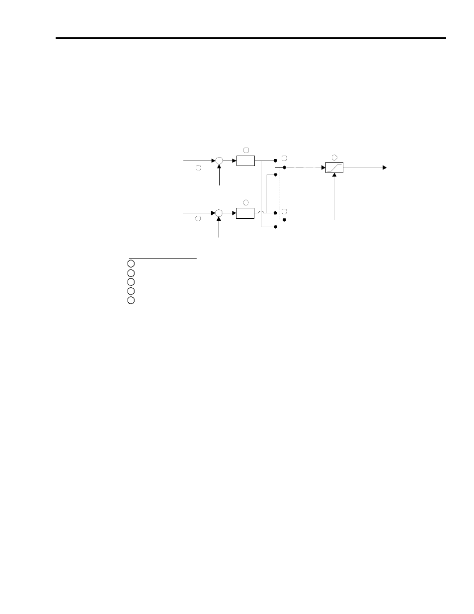
Dual Current Command Mode
Figure 5.26 shows the block diagram for the dual current mode of the
Ultra1500:
Figure 5.26
Dual Current Mode Block Diagram
In this operating mode, an external controller performs all commutation
functions, and the Ultra1500 drive functions as a simple three-phase current
regulator.
• If the command polarity is set to Normal, the U phase current command
comes from the analog velocity input and the W phase current command
comes from the analog current input.
• If the command polarity is set to Inverted, the U phase current command
comes from the analog current input and the W phase current command
comes from the analog velocity input.
The current command limit is set to the minimum of the following:
• Positive / Negative Internal Current Limit,
• Positive / Negative External Current Limit,
• Stopping Current (if active), and
• Drive Peak / Motor Peak Current Rating.
Block/Switch definitions shown in Figure 5.26 refer to the Ultraware parameter names where applicable.
+
+
Ana log Velocity
Co mman d (V olts)
K
c
Analo g V elocity
Command
Offset (V olts)
3
Block/Switch Definitions:
1
Mode Configuration : Analog : Velocity Com mand Offset
2
Mode Configuration : Analog : Current Command Offset
3
Mode Configuration : Analog : Current Scale
4
Main Drive Window : Command Polarity
5
Main Drive Window : Current Limits; Main Drive Window : Stopping Functions : Maximum Stopping Current
5
UV W P hase Curren t
Command to
Current Regu lato r
Ph ase Curren t
Cmd Amplitu de
L imit
1
+
+
Analog Current
Command (Vo lts)
K
c
A nalog Current
Comma nd
O ffset (Volts)
3
2
4
4
U Phase
Current
Co mman d
W P hase
Curren t
Command