5 volt encoder power supply, Understanding the ultra1500 serial interface, 5 volt encoder power supply -23 – Rockwell Automation 2092-DAx Ultra1500 User Manual User Manual
Page 53
Publication 2092-UM001D-EN-P — July 2005
Ultra1500 Connector Data
2-23
5 Volt Encoder Power Supply
All Ultra1500 drives supply 5V dc for the operation of the encoder. The
following table provides a description of the auxiliary encoder power supply.
Understanding the
Ultra1500 Serial Interface
The Ultra1500 includes one serial port that implements a proprietary binary
protocol for serial communication. The RS-232 interface operates at a fixed
38,400 baud, with 8 data bits, no parity, and one stop bit.
Understanding Ultra1500
Power and Ground
Connections
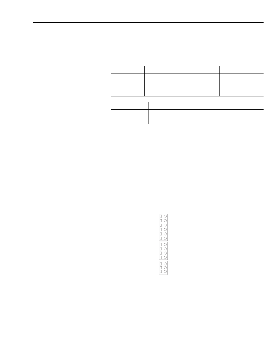
The Ultra1500 has three single-row, spring clamp connectors (six, four, and
three position) that provide access to the drive’s power system. Refer to Figure
2.1 on page 2-2 for the location of these terminals.
Figure 2.23
Ultra1500 Power Terminals
A simplified diagram of the power circuitry internal to the drive is shown in
Figure 2.24.
Parameter
Description
Minimum
Maximum
Output Voltage
Voltage range of the external power supply for
proper operation of an encoder.
4.75V 5.25V
Output Current
Current draw from the external power supply for
the encoder.
—
150 mA
Pin
Signal
Description
CN2-20
EPWR
Encoder Power Out (+5V)
CN2-1 ECOM Encoder
Ground
U
V
W
P1
P2
B1
B2
L1
L2
L2C
DC-
L3
L1C
L1 – Main AC Power
P1 – Diode Bridge
U – Motor Power
L2 – Main AC Power
L3 – Main AC Power
L1C – Control AC Power
L2C – Control AC Power
N – DC Bus Negative
1
P2 – DC Bus Positive
B1 – Shunt Resistor +
B2 – Shunt Resistor -
V – Motor Power
W – Motor Power
Input Power Terminals
DC Bus and
Shunt Power Terminals
Motor Power Terminals
1 DC Bus Negative is labelled DC- on the removable connector, but N on the drive cover.