Index pulses, Index pulses -22 – Rockwell Automation 2092-DAx Ultra1500 User Manual User Manual
Page 52
Publication 2092-UM001D-EN-P — July 2005
2-22
Ultra1500 Connector Data
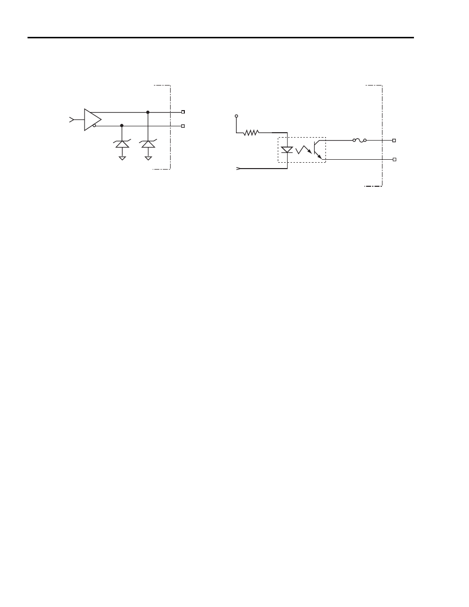
Figure 2.22
Motor Encoder Outputs
Index Pulses
The Ultra1500 has two separate differential outputs that provide an index
pulse for use with controllers. In the case of a rotary motor with a serial
encoder, the marker pulse is generated in the drive hardware.
• The differential buffered encoder output, Channel IM+ and Channel IM-
(CN1-33 and CN1-34), provide a buffered version of the encoder marker
pulse. As with the AM and BM channel outputs, the time duration of the
signal states depend on the rotational speed.
• The Z-Pulse differential outputs, (CN1-17 and CN1-18), provide an
opto-isolated marker signal that has a minimum time duration of 800
µsec.
At low speeds, the two marker outputs are identical, however at high
speeds the Z-pulse output will enforce a minimum time duration of 800
µsec.
On incremental motor encoders, the index output (IM+ and IM-) is a buffered
version of the encoder index, and it is not altered. However, the AM and BM
signals are both inverted from the encoders signals. If the controller requires
non-inverted AM and BM outputs (e.g., if the controller gates the index with a
particular AM/BM state), the + and - signals of the AM and BM outputs can
be swapped before connecting to the controller.
With serial encoders, the index output (IM+ and IM-) is generated by the drive
hardware, since the serial encoders do not have an actual index signal. The
generated index signal is two counts in width, and phasing to a particular A/B
state is arbitrary. The index signal is generated at the zero location of the
fractional revolutions for the encoder.
AM-
AM+
75174
16V
16V
Logic Ground
Logic Ground
Ultra1500 Drive
AM, BM, and IM Outputs
Z-Pulse-
TLP127
330
Ω
Z-Pulse+
0.5A Fuse
Logic Power
Ultra1500 Drive
Z-Pulse Output