Establishing noise zones, Establishing noise zones -14 – Rockwell Automation 2092-DAx Ultra1500 User Manual User Manual
Page 26
Publication 2092-UM001D-EN-P — July 2005
1-14
Installing Your Ultra1500
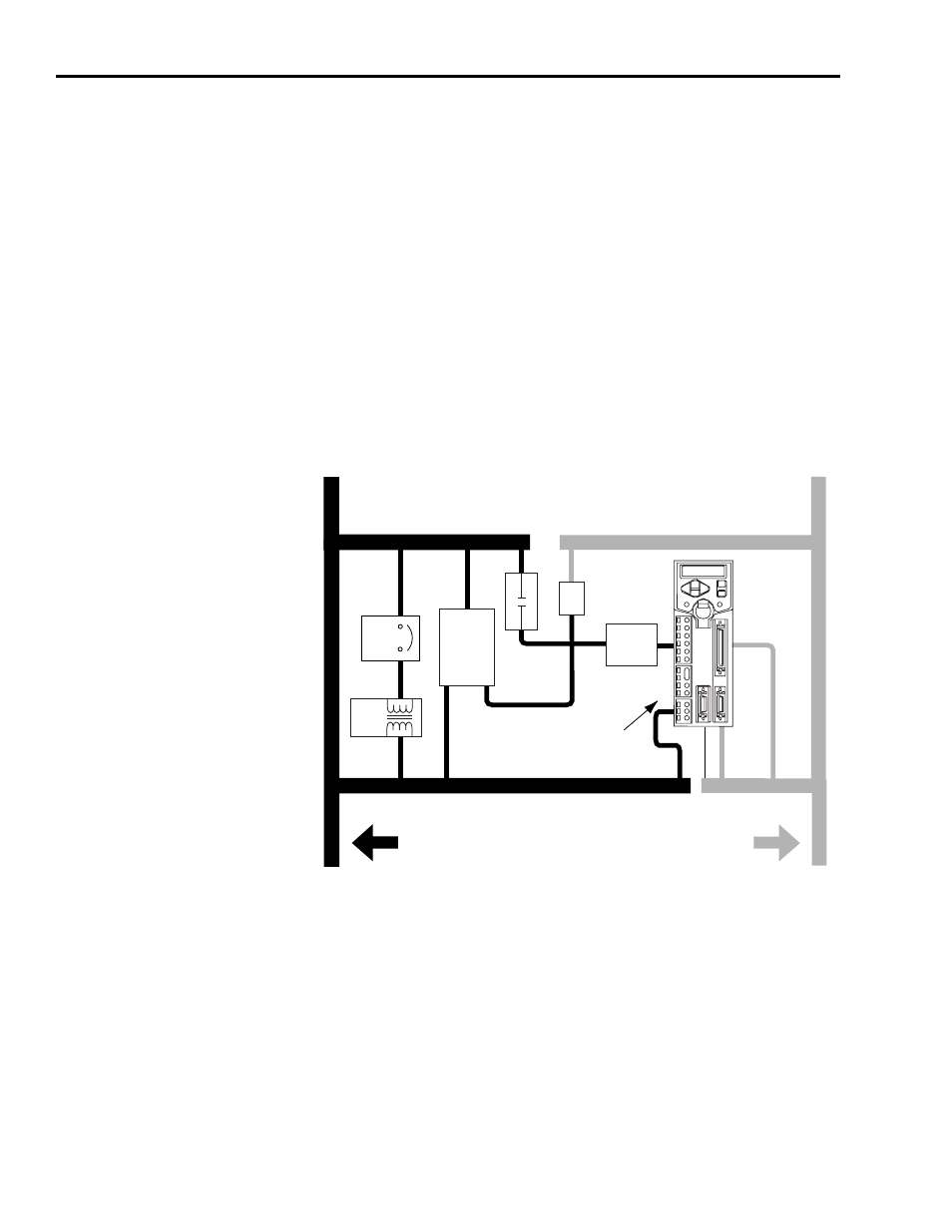
Establishing Noise Zones
Observe the following guidelines when laying out your panel (refer to Figure
1.5 for zone locations).
• The clean zone (C) is above and beneath the Ultra1500 and includes CN1,
CN2, and CN3 signals, and the DC filter (grey wireways).
• The dirty zone (D) is left of the Ultra1500 (black wireways) and includes
the circuit breakers, transformer, AC line filter, contactors, 24V dc power
supply, and motor (output) power cables.
• The very dirty zone (VD) is limited to where the AC line (EMC) filter AC
output jumpers over to the Ultra1500. Shielded cable is required only if
the very dirty cables enter a wireway.
Figure 1.5
Establishing Noise Zones
1 If I/O cable contains (dirty) relay wires, route cable with motor (output) power wires in dirty wireway.
2 This is a clean 24V dc available for CN1 I/O power supply. The 24V enters the clean wireway and exits to the right.
3 This is a dirty 24V dc available for motor brakes and contactors. The 24V enters the dirty wireway and exits to the
left.
(1)
C
D
D
VD
D
D
C
CN1
CN2
D
CN3
I/O Cable
1
Route Motor Power
Shielded Cable
Route Encoder/Analog/Registration
Shielded Cable
Dirty Wireway
Clean Wireway
Motor Power Cables
24V
Power Supply
Circuit
Breaker
XFMR
AC
Line Filter
DC
Filter
Contactors
Very dirty EMC filter connections
segregated (not in wireway)
Ultra1500
Mount AC line
filter as close
to the drive as
possible
24V dc
3
24V dc
2