Rockwell Automation 2092-DAx Ultra1500 User Manual User Manual
Page 118
Publication 2092-UM001D-EN-P — July 2005
5-38
Ultra1500 Application Examples
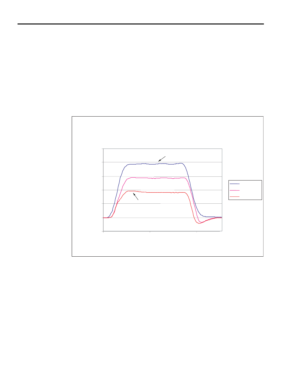
Figure 5.18 shows the effect of varying the offset value on the position error
during a typical motion profile. In the first figure, the drive was operated with
the position regulator default gain settings, (Kp = 20, Kff = 0), and the
threshold was set to 2000 counts. The plot clearly illustrates that the offset
reduces the steady state error by a fixed amount, and increasing the offset
further reduces the error. Using the offset also results in some overshoot at the
end of the deceleration when the offset value is removed from the position
regulator output (when counts < 2000). This overshoot increases with larger
offsets.
Figure 5.18
Position Regulator Response During Move with Varied Error Offset
In Figure 5.19, Kff = 100 and the steady state error is almost eliminated by use
of the feedforward gain. Applying the offset does decrease the amount of
error during the acceleration and deceleration but results in slightly more
overshoot at the end of the deceleration. Varying the offset and threshold
values to other values not illustrated here can affect the position error in
substantially different ways. For example, setting the offset value to small
values can result in a forced oscillation of the position error around zero when
the shaft should be stationary.
Offset = 0
Offset = 200
Offset = 400
Time (msec)
0
50
100
-4000
0
4000
20000
12000
Follower Positioin (counts)
8000
High Error Output Offset = 0
16000
High Error Output Offset = 400