Controllogix 1756-m02ae system, Control connections, Controllogix 1756-m02ae system -2 – Rockwell Automation 2092-DAx Ultra1500 User Manual User Manual
Page 82: Control connections -2
Publication 2092-UM001D-EN-P — July 2005
5-2
Ultra1500 Application Examples
ControlLogix 1756-M02AE
System
The Ultra1500 can be integrated into an Allen-Bradley ControlLogix PLC
system using the 1756-M02AE Analog Encoder Servo Module. In this
configuration, the drive can be operated in either Analog Velocity or Analog
Current mode.
The Ultra1500 drive can be connected to a TL-Series motor with a
battery-backed, multi-turn serial absolute encoder, and the absolute position
can be provided to the ControlLogix system via the buffered encoder feedback
connections. Refer to Absolute Positioning on page 5-16 for details on extracting
the absolute position from the drive to a controller.
Control Connections
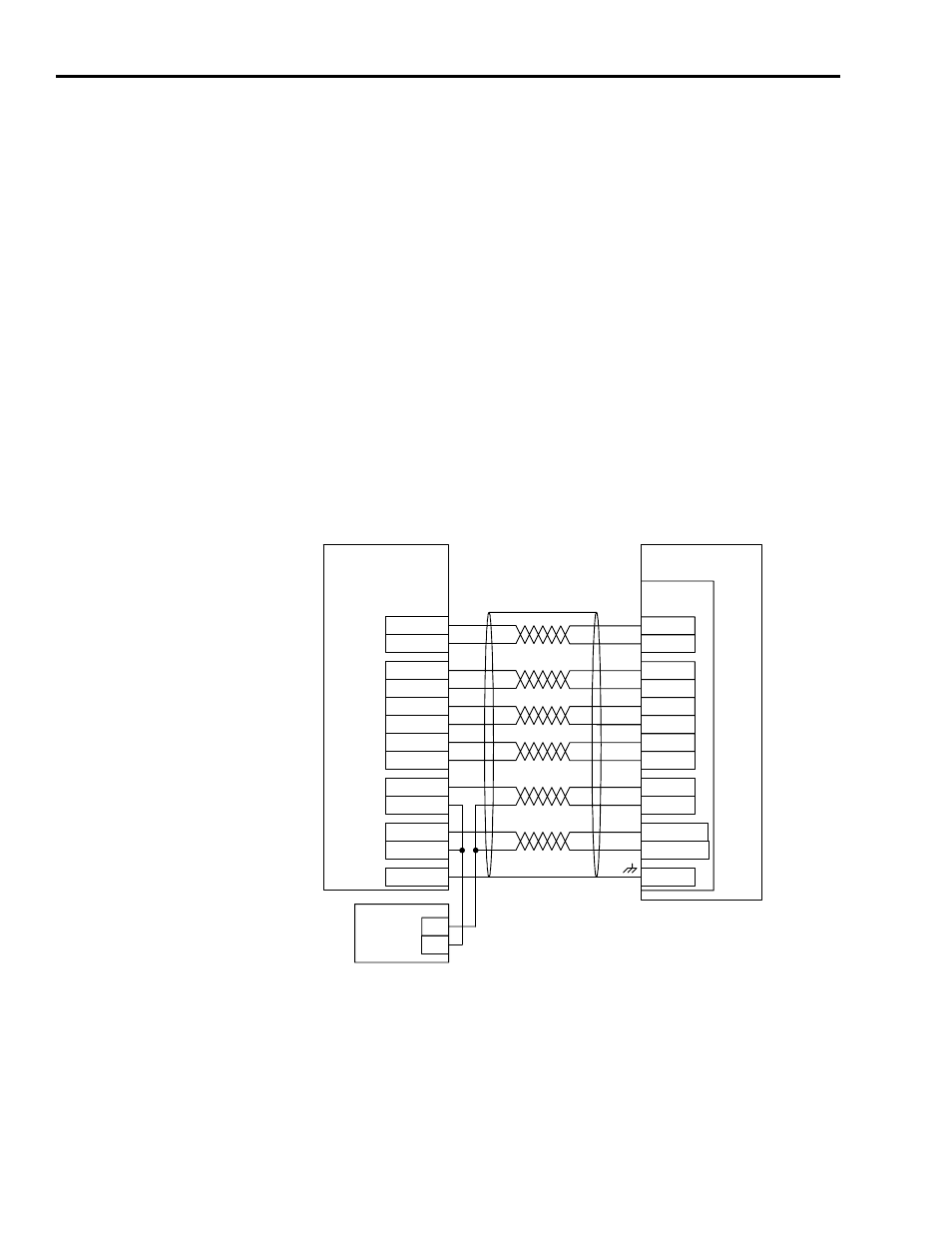
Figure 5.1 shows the recommended control wiring connections between the
1756-M02AE and the Ultra1500 when the drive is operated in Analog Current
mode
Figure 5.1
Ultra1500 and 1756-M02AE Control Wiring Example.
In Figure 5.1, the 1756-M02AE provides a current command to the drive and
the 1756-M02AE closes the velocity loop. Alternatively, the 1756-M02AE can
provide a velocity command to the drive, and the drive can be responsible for
the velocity loop closure. In that case, the 1756-M02AE command outputs
should be connected to CN1 pins 19 and 20, instead of CN1 pins 21 and 22,
and the Ultra1500 should be operated in Analog Velocity mode.
1756-M02AE
+OUT
-OUT
+ENABLE
ULTRA1500
-ENABLE
DRVFLT+
IN_COM
24V
POWER
SUPPLY
ICMD+
ICMD-
INPUT1
24V IN
OUTPUT2-
OUTPUT2+
21
22
3
1
44
43
CHASSIS
SHIELD
CN1
+CHA
-CHA
AM+
AM-
29
30
+CHB
-CHB
BM+
BM-
31
32
+CHZ
-CHZ
IM+
IM-
33
34
+
-