Hall inputs, Hall inputs -15, To figure 2.11 – Rockwell Automation 2092-DAx Ultra1500 User Manual User Manual
Page 45
Publication 2092-UM001D-EN-P — July 2005
Ultra1500 Connector Data
2-15
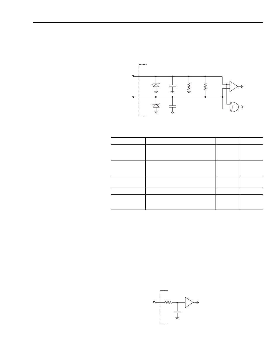
line loss detection using exclusive-OR gates that can be disabled in Ultraware if
electrical noise results in nuisance faults.
Figure 2.11
Schematic of the Motor Encoder Inputs
The following table provides a description of the A, B, and I inputs.
Hall Inputs
The Ultra1500 uses Hall signals to initialize the commutation angle for
sinusoidal commutation with incremental encoders. Hall signals must be
single-ended and can be either open collector type or TTL type. Figure 2.12
shows the configuration of the Hall inputs (S1, S2, and S3).
Figure 2.12
Hall Input Configuration
Parameter
Description
Minimum
Maximum
A, B, and I
ON State
Input Voltage
Input voltage difference between the + input
and the - input that is detected as an ON
state.
+1.0V
+7.0V
A, B, and I
OFF State
Input Voltage
Input voltage difference between the + input
and the - input that is detected as an OFF
state.
-1.0V
-7.0V
Common Mode
Input Voltage
Potential difference between any encoder
signal and logic ground.
-7.0V
+12.0V
DC Current Draw
Current draw into the + or - input.
-30 mA
30 mA
A, B Input Signal
Frequency
Frequency of the A or B signal inputs. The
count frequency is 4 times this frequency,
since the circuitry counts all four transitions.
—
4 MHz
-
+
A-
A+
220
Ω
DS34C86
74HCT86
A
A Line Loss
13V
13V
0.001
µF
0.001
µF
4.7 k
Ω
Ultra1500 Drive
S1
0.01
µF
74HCT14
Logic Ground
1 k
Ω
Ultra1500 Drive