Rockwell Automation 2092-DAx Ultra1500 User Manual User Manual
Page 71
Publication 2092-UM001D-EN-P — July 2005
Connecting Your Ultra1500
3-13
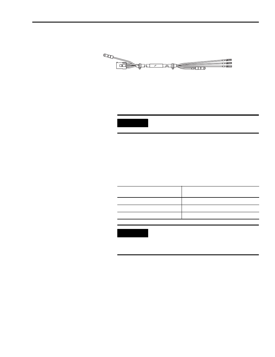
Figure 3.10
Motor Power Cable for TL-Series Motors (2090-DANPT-16Sxx)
To wire power from the drive to your motor:
1. Route the motor power cable to your Ultra1500 drive.
2. Ground the Shield lug on the motor end of the 2090-DANPT-16Sxx cable
assembly to an unpainted, metallic machine frame near the motor. Refer
to Bonding Modules on page 1-12 for recommended methods..
3. Using the connector tool (Wago 231-131 shown in Figure 3.9) provided
with the drive, open the clamp for each of the terminal locations and
attach wires as shown in the table below.
4. Connect the Ground wire to a terminal screw on the drive, and tighten the
ground terminal screw to 1.25 Nm (11 lbs-in.).
5. Gently pull on each wire to make sure it does not come out of its terminal.
Re-insert any loose wires.
6. Re-insert the Motor Power connector on the terminal block. The
connector is keyed to prevent incorrect installation.
U-Phase - Brown
V-Phase - Black
W-Phase - Blue
Shield - Green
Ground - Green
Motor End
Terminal End
IMPORTANT
To ensure system performance, run wires and cables in
the wireways as established in Chapter 1.
Insert the motor power wires from a
TL-Series servo motor:
Into this terminal on the
4-pin Motor Power Connector
U / Brown
U
V / Black
V
W / Blue
W
IMPORTANT
Ensure motor power is wired with proper phasing
relative to the motor terminals. On some motors, the
motor leads may be labeled R, S, and T which
correspond to U, V, and W respectively.