Rockwell Automation 2092-DAx Ultra1500 User Manual User Manual
Page 67
Publication 2092-UM001D-EN-P — July 2005
Connecting Your Ultra1500
3-9
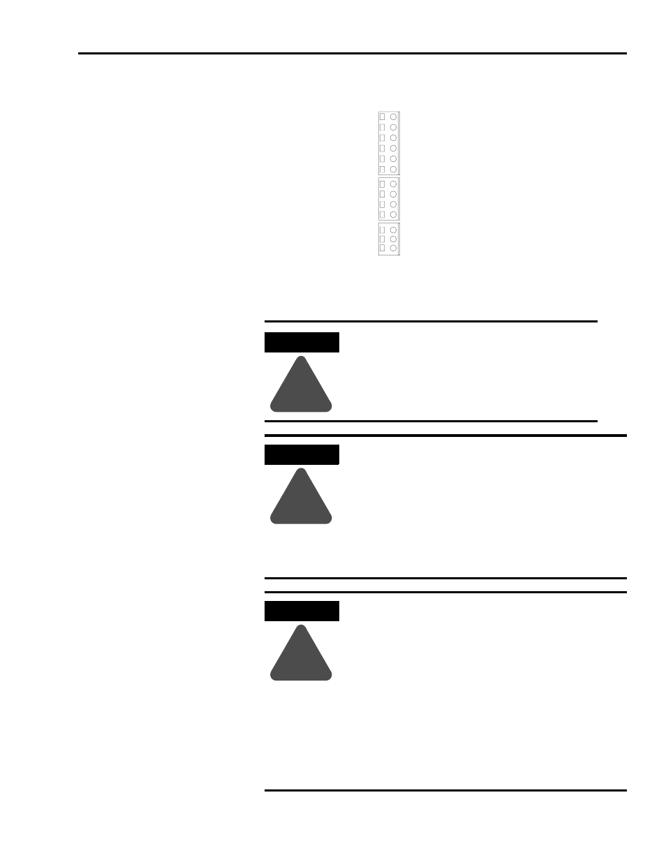
Figure 3.7
Ultra1500 Power Terminal Positions
ATTENTION
!
The N terminal (labelled DC- on the removable
connector) IS NOT an Input Power connection.
ATTENTION
!
This drive contains ESD (Electrostatic Discharge) sensitive
parts and assemblies. You are required to follow static
control precautions when you install, test, service, or repair
this assembly. If you do not follow ESD control
procedures, components can be damaged. If you are not
familiar with static control procedures, refer to
Allen-Bradley publication 8000-4.5.2, Guarding Against
Electrostatic Damage or any other applicable ESD Protection
Handbook.
ATTENTION
!
To avoid personal injury and/or equipment damage, ensure
installation complies with specifications regarding wire
types, conductor sizes, branch circuit protection, and
disconnect devices. The National Electrical Code (NEC)
and local codes outline provisions for safely installing
electrical equipment.
To avoid personal injury and/or equipment damage, ensure
motor power connectors are used for connection purposes
only. Do not use them to turn the unit on and off.
To avoid personal injury and/or equipment damage, ensure
shielded power cables are grounded to prevent potentially
high voltages on the shield.
U
V
W
P1
P2
B1
B2
L1
L2
L2C
DC-
L3
L1C
L1 – Main AC Power
P1 – Diode Bridge
U – Motor Power
L2 – Main AC Power
L3 – Main AC Power
L1C – Control AC Power
L2C – Control AC Power
N – DC Bus Negative
1
P2 – DC Bus Positive
B1 – Shunt Resistor +
B2 – Shunt Resistor -
V – Motor Power
W – Motor Power
Main Input Power Terminals
DC Bus and
Shunt Power Terminals
Motor Power Terminals
1 DC Bus Negative is labelled DC- on the removable connector, but N on the drive cover.