Input power connectors, Main power - l1, l2, and l3, Input power connectors -24 – Rockwell Automation 2092-DAx Ultra1500 User Manual User Manual
Page 54: Main power – l1, l2, and l3 -24, Main power – l1, l2, and l3, Attention
Publication 2092-UM001D-EN-P — July 2005
2-24
Ultra1500 Connector Data
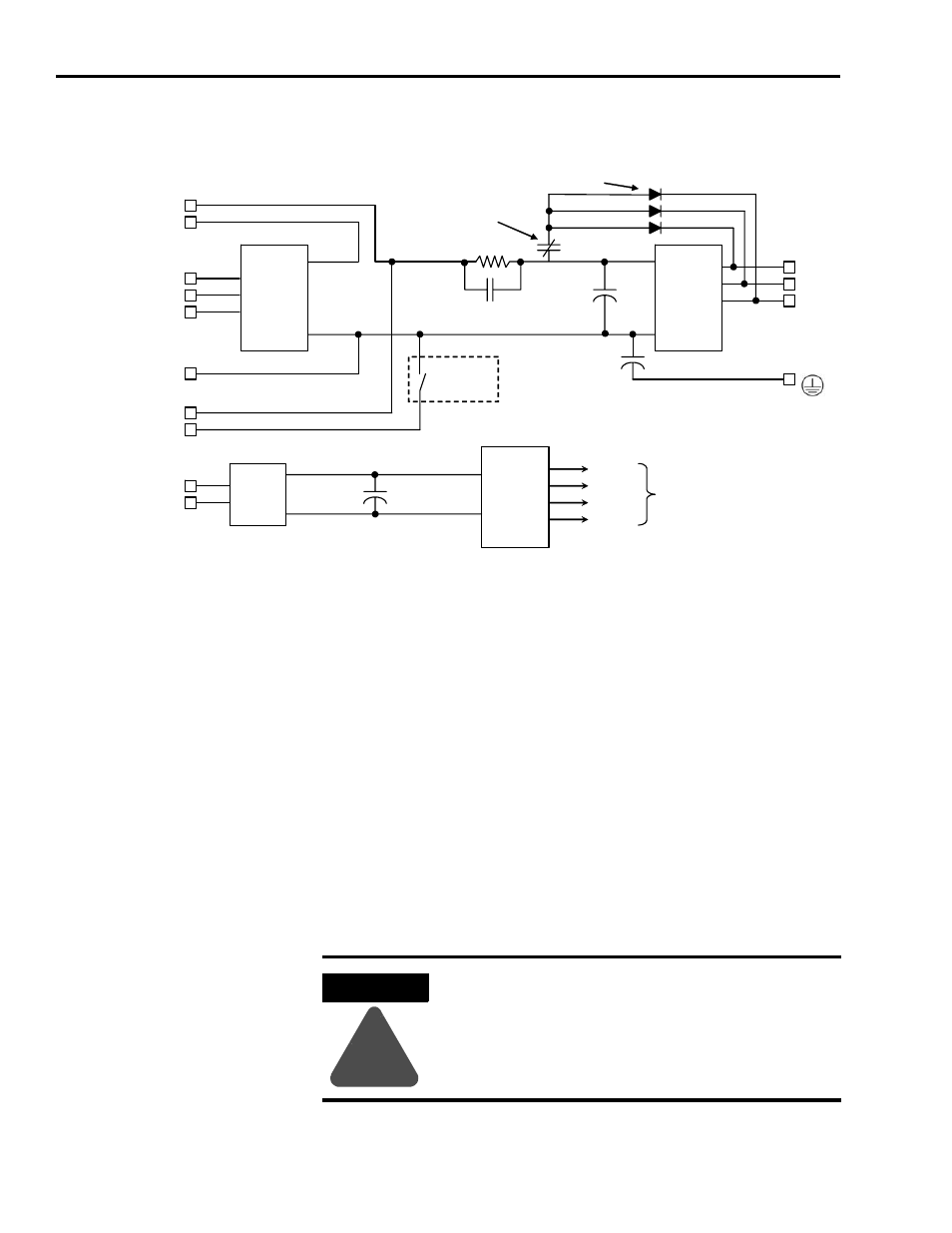
Figure 2.24
Simplified Ultra1500 Internal Power Circuitry
Input Power Connectors
The following power connections are made to an Ultra1500 drive through a six
position terminal connector.
Main Power – L1, L2, and L3
L1 and L2 are single-phase main AC power input connections for the
2092-DA1, 2092-DA2, and 2092 -DA3 drives. L1, L2, and L3 are three-phase
main AC power input connections for the 2092-DA4 and 2092 -DA5.
Note: The L3 terminal is not used with the 2092-DA1, 2092-DA2, and
2092-DA3 models, as they require single-phase input power.
Diode
Bridge
Integrated
Power
Module
L1
L2
L3
U
V
W
Soft-Start
Relay
Dynamic
Brake Relay
NTC
DC
BUS
+
-
C
BUS
P2
P1
N
B1
B2
Shunt
Circuitry
Dynamic Brake Diodes
Switch
Mode
Power
Supply
L1C
L2C
+5V
+12V
-12V
IPM
Power for
Control
Circuitry
Diode
Bridge
Note: DC Bus Negative is labelled N on the drive cover, but DC- on the removable connector.
ATTENTION
!
The main AC power inputs should not be removed and
re-applied at a rate exceeding once every 2 minutes. Ensure
that your control timing guarantees this minimum period to
avoid damaging the drive.