Rockwell Automation 2092-DAx Ultra1500 User Manual User Manual
Page 103
Publication 2092-UM001D-EN-P — July 2005
Ultra1500 Application Examples
5-23
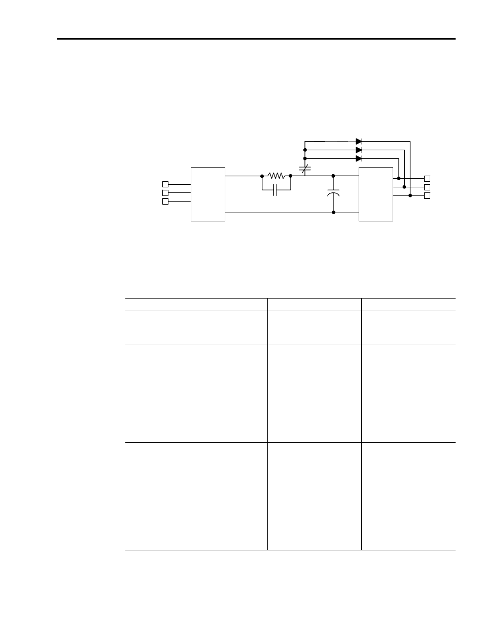
through diodes. The diodes in the integrated power module (IPM) in
conjunction with the three diodes shown in the figure, effectively short the
motor windings to each other and also to the positive terminal of the DC bus.
Figure 5.7
Ultra1500 Dynamic Braking Relay Circuitry
In the figure, it is important to notice that the dynamic brake relay contacts
utilize the same controlling coil as the soft-start thermistor circuitry. This
interdependence can be important in certain applications. The possible states
of the dynamic brake and soft start contacts are as follows:
Diode
Bridge
Integrated
Power
Module
L1
L2
L3
U
V
W
NO
NC
NTC
DC
BUS
+
-
C
BUS
Condition
Soft-Start Circuitry
Dynamic Brake Circuitry
Control power not applied to drive.
The thermistor isolates the bus
capacitance from the AC inputs
and the current is restricted by the
thermistor impedance.
The motor windings are shorted
together to the positive DC bus
level through diodes.
Control power applied to drive, and the relay coil is
not energized by the firmware because one of the
following conditions exists:
1. Drive is disabled and Fault and Disable Braking
selection is Brake and Hold.
2. Drive is disabled, Fault and Disable Braking
selection is Brake and Release, and motor speed
is nonzero.
3. Drive is disabled, Fault and Disable Braking
selection is Free Stop and Hold, and the motor is
stopped.
The thermistor isolates the bus
capacitance from the AC inputs
and the current is restricted by the
thermistor impedance.
The motor windings are shorted
together to the positive DC bus
level through diodes.
Control power applied to drive, and the relay coil is
energized by the firmware because one of the
following conditions exists:
1. Drive is enabled.
2. Drive is disabled and Fault and Disable Braking
selection is Free Stop.
3. Drive is disabled, Fault and Disable Braking
selection is Free Stop and Hold, and motor speed
is nonzero.
4. Drive is disabled, Fault and Disable Braking
selection is Brake and Release, and the motor is
stopped.
The thermistor is shorted out by
the relay contacts, and the current
between the AC inputs and the
bus capacitance is not restricted.
The motor windings are isolated
from each other.