8 – clock stretching, 9 – smbus timeout, Clock stretching – Maxim Integrated DS4830 Optical Microcontroller User Manual
Page 93: Smbus timeout, Ds4830 user’s guide
DS4830 User’s Guide
93
11.1.8
– Clock Stretching
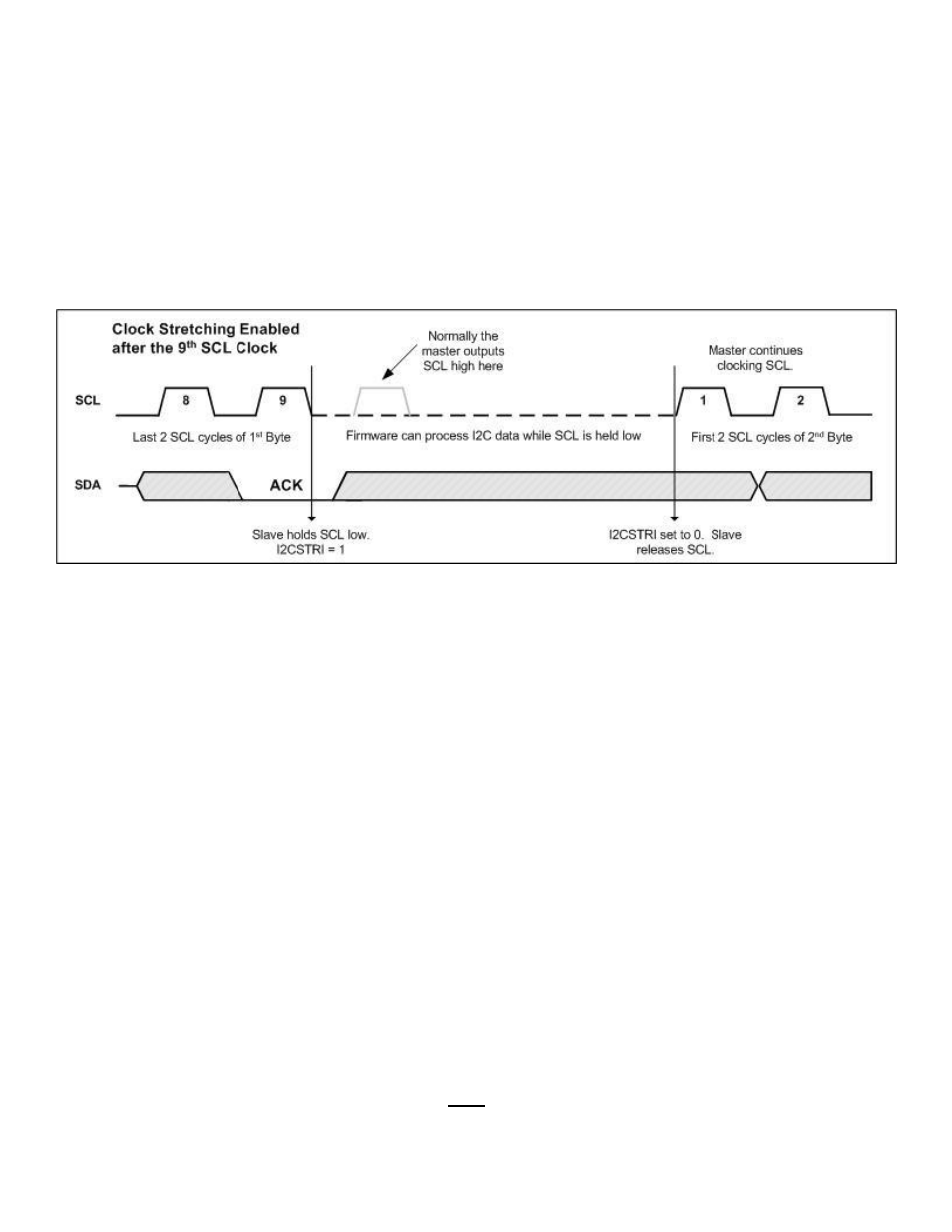
If a slave device cannot receive or transmit another complete byte of data, it may hold SCL low, forcing the master to wait.
Data transfer will continue when the slave is ready for another byte of data and releases SCL.
The I
2
C slave controller is capable of holding SCL low at the completion of each byte being transferred. If the I2C Clock
Stretch Enable bit (I2CSTREN) is set to a 1, the I2C controller will hold SCL low after the clock pulse defined by the I
2
C
Clock Stretch Select bit (I2CSTRS). If I2CSTRS=0, the I
2
C controller will hold SCL low after the falling edge of the 9
th
clock pulse. Otherwise, if I2CSTRS=1, the I
2
C controller will hold SCL low after the falling edge of the 8th clock pulse.
When the I
2
C controller is holding SCL low, the I
2
C Clock Stretch Interrupt bit (I2CSTRI) will be set. The I
2
C slave
controller will hold SCL low until I2CSTRI is cleared to '0' by software. Figure 11-3 shows the I
2
C slave controller clock
stretching after receiving the 9
th
clock of a byte.
Figure 11-3: Slave I
2
C Clock Stretching
Normally when the I
2
C slave controller is receiving data, the value of I2CACK will be output after the 8th clock falling
edge. However, if clock stretching is enabled after the 8
th
clock, the I
2
C slave controller will continually output the I2CACK
bit until clock stretching is released by software. This allows software time to inspect data that was received before
responding with an appropriate acknowledge bit.
Most applications that use the DS4830’s I
2
C slave controller will need to use clock stretching. Generally the application
will be set to only respond to interrupts from the I
2
C slave controller, thus not having to continuously poll the slave I
2
C
controller. After each byte transfer is complete, the I
2
C slave controller needs to either read the received byte from
I2CBUF_S or write the next byte to transmit to I2CBUF_S. Without using clock stretching, the host can begin clocking the
next byte before the I
2
C slave controller is prepared. A few conditions that may require clock stretching to be enabled are
listed below.
When a slave address match is made and the R/W bit is set, the I
2
C slave controller will be expected to transmit a
byte of data to the host. This byte of data needs to be written to I2CBUF_S after the 8
th
clock of the slave
address (when I2CBUSY is cleared) and prior to the 1
st
clock of the data byte. If clock stretching is not used,
software may not be able to write the correct data into I2CBUF_S prior to the 1
st
clock of the data byte.
Following the transmission of one byte of data to the host, another byte may be requested by the host sending an
ACK bit. The I
2
C slave controller has between the 9
th
clock of the first data byte (when I2CBUSY is cleared) and
the 1
st
clock of the second byte to write to I2CBUF_S. If clock stretching is not used, software may not be able to
write the next byte to I2CBUF_S prior to the 1
st
clock of the second byte.
After a byte is received by the I
2
C slave controller it may be necessary to stretch the clock. This will allow
software time to read the byte from I2CBUF_S and do any data processing. Without using clock stretching, there
is a chance that a second byte could be sent prior to the software reading the first byte, creating a receive overrun
condition. Any additional data that is sent after this time will be lost.
11.1.9
– SMBus Timeout
The I
2
C slave controller can also be used for SMBus or PMBus
™ communication. To maintain SMBus compatibility, a
30ms timer is implemented by the I
2
C slave controller. The purpose of this timer is to issue a timeout interrupt when SCL
is low for greater than 30ms. The timer only starts when none of the following conditions are true: