Section 9 – quick trip (fast comparator), 1 – detailed description, Section 9 – Maxim Integrated DS4830 Optical Microcontroller User Manual
Page 68: Quick trip (fast comparator), Detailed description, Ds4830 user’s guide, Figure 9-1: quick trip functional block diagram, Qtdata[15:0
DS4830 User’s Guide
68
SECTION 9
– QUICK TRIP (FAST COMPARATOR)
The DS4830 has 16 8-bit quick trips with 16-input Analog MUX (Figure 9-1). The MUX selects the quick trip analog input
from 16 external channels. The quick trip external channels can be configured to operate as eight fully differential inputs
or sixteen single-ended inputs. The quick trip monitors all configured quick trip channels in a round robin sequence.
QT CONFIGURATIONS
ADC-S0
ADC-S1
ADC-S14
ADC-S15
A
N
A
L
O
G
M
U
X
QT SEQUENCER
Q
T
S
T
A
R
T
Q
T
E
N
D
Q
T
E
N
QT HIGH
THRESHOLD
QT LOW
THRESHOLD
CHSEL[3:0]
DIFF
Digital MUX
8-Bit
Internal
DAC
HT Register[0]
HT Register[14]
HT Register[1]
HT Register[15]
16 High Threshold
Registers
LT Register[0]
LT Register[14]
LT Register[1]
LT Register[15]
16 Low Threshold
Registers
LIST REGISTER[0]
LIST REGISTER[14]
LIST REGISTER[1]
LIST REGISTER[15]
16 List Configurations
5 bit Each
LTI / HTI
LTIE / HTIE
Interrupt
Q
T
C
L
O
C
K
QTDATA[15:0]
Comparator
QT- 2.42V
Internal
Reference
.
.
.
RW_LST = 0
LTHT = 0
RW_LST = 1
.
.
.
.
.
.
RW_LST = 0
LTHT = 1
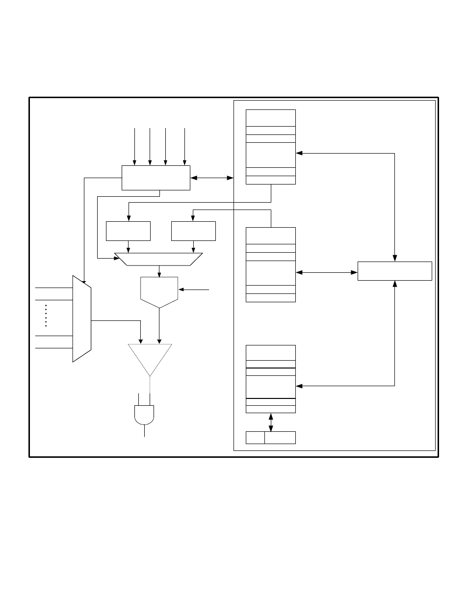
Figure 9-1: Quick Trip Functional Block Diagram
9.1
– Detailed Description
As shown in Figure 9-1, the DS4830 Quick Trip (QT) controller has a 16-input analog MUX and Quick Trip Sequencer.
The QT sequencer creates a list of configurations and sets user defined low and high threshold for external channels. The
quick trip controller has 16 low trip threshold and 16 high trip threshold internal registers.
The Quick Trip Control Register (QTCN) has two bits RW_LST and LTHT which are used to configure thresholds and list
creation. The QTIDX[3:0] bits (located in the QTCN register) together with LTHT and RW_LST bits select the source or
destination address for the QTDATA register access. Figure 9-1 illustrates the threshold configuration and list creation.