Ds4830 user’s guide, 3 – multiplier operand b register (mb), 4 – multiplier accumulator 2 register (mc2) – Maxim Integrated DS4830 Optical Microcontroller User Manual
Page 144: 5 – multiplier accumulator 1 register (mc1), 6 – multiplier accumulator 0 register (mc0), 7 – multiplier read register 1 (mc1r), 8 – multiplier read register 0 (mc0r)
DS4830 User’s Guide
144
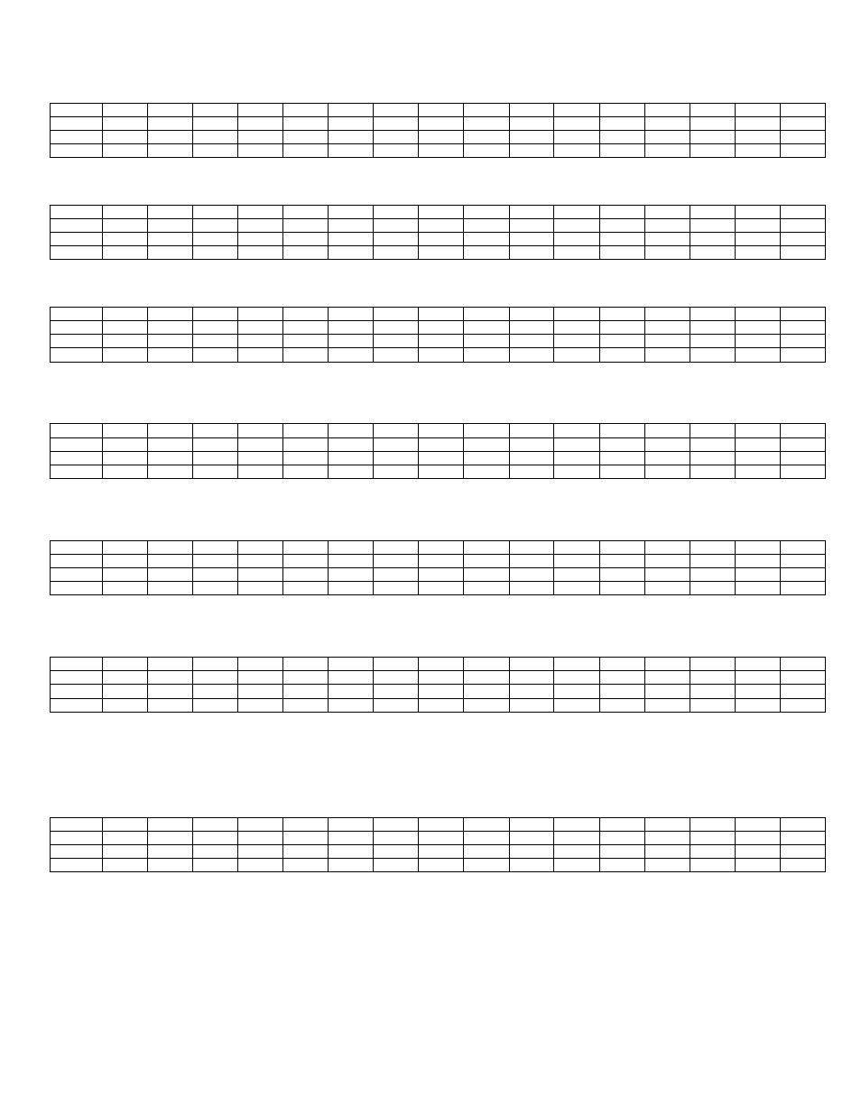
18.5.2
– Multiplier Operand A Register (MA)
Bit
15
14
13
12
11
10
9
8
7
6
5
4
3
2
1
0
Name
MA.15
MA.14
MA.13
MA.12
MA.11
MA.10
MA.9
MA.8
MA.7
MA.6
MA.5
MA.4
MA.3
MA.2
MA.1
MA.0
Reset
0
0
0
0
0
0
0
0
0
0
0
0
0
0
0
0
Access
rw
rw
rw
rw
rw
rw
rw
rw
rw
rw
rw
rw
rw
rw
rw
rw
Multiplier Operand A: This operand A register is used by the application code to load 16-bit values for multiplier operations.
18.5.3
– Multiplier Operand B Register (MB)
Bit
15
14
13
12
11
10
9
8
7
6
5
4
3
2
1
0
Name
MB.15
MB.14
MB.13
MB.12
MB.11
MB.10
MB.9
MB.8
MB.7
MB.6
MB.5
MB.4
MB.3
MB.2
MB.1
MB.0
Reset
0
0
0
0
0
0
0
0
0
0
0
0
0
0
0
0
Access
rw
rw
rw
rw
rw
rw
rw
rw
rw
rw
rw
rw
rw
rw
rw
rw
Multiplier Operand B: This operand B register is used by the application code to load 16-bit values for multiplier operations.
18.5.4
– Multiplier Accumulator 2 Register (MC2)
Bit
15
14
13
12
11
10
9
8
7
6
5
4
3
2
1
0
Name
MC2.15
MC2.14
MC2.13
MC2.12
MC2.11
MC2.10
MC2.9
MC2.8
MC2.7
MC2.6
MC2.5
MC2.4
MC2.3
MC2.2
MC2.1
MC2.0
Reset
0
0
0
0
0
0
0
0
0
0
0
0
0
0
0
0
Access
rw
rw
rw
rw
rw
rw
rw
rw
rw
rw
rw
rw
rw
rw
rw
rw
Multiplier Accumulator 2 Register: The MC2 register represents the two most significant bytes of the accumulator register. The 48-
bit accumulator is formed by MC2, MC1 and MC0. For a signed operation, the most significant bit of this register is the sign bit.
18.5.5
– Multiplier Accumulator 1 Register (MC1)
Bit
15
14
13
12
11
10
9
8
7
6
5
4
3
2
1
0
Name
MC1.15
MC1.14
MC1.13
MC1.12
MC1.11
MC1.10
MC1.9
MC1.8
MC1.7
MC1.6
MC1.5
MC1.4
MC1.3
MC1.2
MC1.1
MC1.0
Reset
0
0
0
0
0
0
0
0
0
0
0
0
0
0
0
0
Access
rw
rw
rw
rw
rw
rw
rw
rw
rw
rw
rw
rw
rw
rw
rw
rw
Multiplier Accumulator 1 Register: The MC1 register represents bytes 3 and 2 of the accumulator register. The 48-bit accumulator is
formed by MC2, MC1, and MC0.
18.5.6
– Multiplier Accumulator 0 Register (MC0)
Bit
15
14
13
12
11
10
9
8
7
6
5
4
3
2
1
0
Name
MC0.15
MC0.14
MC0.13
MC0.12
MC0.11
MC0.10
MC0.9
MC0.8
MC0.7
MC0.6
MC0.5
MC0.4
MC0.3
MC0.2
MC0.1
MC0.0
Reset
0
0
0
0
0
0
0
0
0
0
0
0
0
0
0
0
Access
rw
rw
rw
rw
rw
rw
rw
rw
rw
rw
rw
rw
rw
rw
rw
rw
Multiplier Accumulator 0 Register: The MC0 register represents the two least significant bytes of the accumulator register. The 48-
bit accumulator is formed by MC2, MC1, and MC0.
18.5.7
– Multiplier Read Register 1 (MC1R)
Bit
15
14
13
12
11
10
9
8
7
6
5
4
3
2
1
0
Name
MC1R.15 MC1R.14 MC1R.13 MC1R.12 MC1R.11 MC1R.10
MC1R.9
MC1R.8
MC1R.7
MC1R.6
MC1R.5
MC1R.4
MC1R.3
MC1R.2
MC1R.1
MC1R.0
Reset
0
0
0
0
0
0
0
0
0
0
0
0
0
0
0
0
Access
rw
rw
rw
rw
rw
rw
rw
rw
rw
rw
rw
rw
rw
rw
rw
rw
Multiplier Read Register 1: The MC1R register represents bytes 3 and 2 from the result of the last operation when MCW = 1 or the
last operation was a multiply or multiply-negate. When MCW = 0 and the last operation was a multiply-accumulate/subtract, the
contents of this register may or may not agree with the contents of MC1 due to the combinatorial nature of the adder. The content of
this register may change if MCNT, MA, MB, or MC[2:0] is changed.
18.5.8
– Multiplier Read Register 0 (MC0R)
Bit
15
14
13
12
11
10
9
8
7
6
5
4
3
2
1
0
Name
MC0R.15 MC0R.14 MC0R.13 MC0R.12 MC0R.11 MC0R.10
MC0R.9
MC0R.8
MC0R.7
MC0R.6
MC0R.5
MC0R.4
MC0R.3
MC0R.2
MC0R.1
MC0R.0
Reset
0
0
0
0
0
0
0
0
0
0
0
0
0
0
0
0
Access
rw
rw
rw
rw
rw
rw
rw
rw
rw
rw
rw
rw
rw
rw
rw
rw
Multiplier Read Register 0: The MC1R register represents bytes 1 and 0 from the result of the last operation when MCW = 1 or the
last operation was a multiply or multiply-negate. When MCW = 0 and the last operation was a multiply-accumulate/subtract, the
contents of this register may or may not agree with the contents of MC0 due to the combinatorial nature of the adder. The content of
this register may change if MCNT, MA, MB or MC[2:0] is changed.