Ds4830 user’s guide – Maxim Integrated DS4830 Optical Microcontroller User Manual
Page 117
DS4830 User’s Guide
117
PWM Output
High Time
32 Cycles
PWM Output
Low Time
96 Cycles
PWM Frame = 512 Cycles
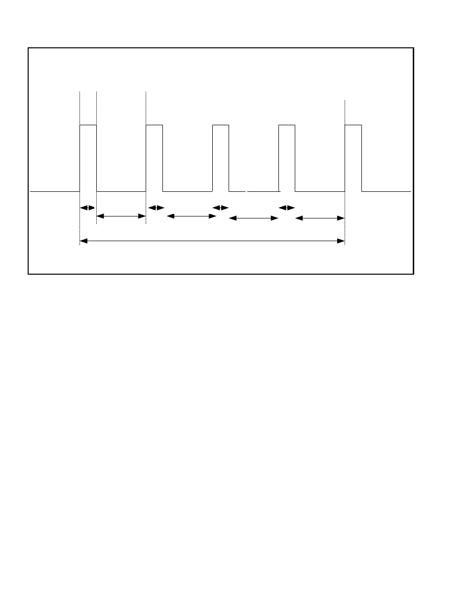
9 bit PWM Operation in 4 Slot pulse spreading mode
DCYCn = 127
Slot 1
Slot 2
Slot 3
Slot 4
PWM Output
High Time
PWM Output
Low Time
PWM Output
Low Time
PWM Output
Low Time
PWM Output
High Time
PWM Output
High Time
Slot 1
Next Cycle
32 Cycles
96 Cycles
32 Cycles
96 Cycles
31 Cycles
97 Cycles
Figure 14-5: 9-bit PWM operation in 4-Slot pulse spreading mode
14.2.3.2
– 32-Slot Pulse Spreading Operation
This mode is selected when the PS4 and PS32 bits are set to ‘1’ and is operational only when the PWM channel is set to
12 bits of resolution. In this mode, the PWM controller distributes the duty cycle over 32 equal slots. Similarly, the PWM
controller distributes the PWM Frame over 32 equal slots. By doing this, the PWM output frequency becomes 32 times the
PWM Frame frequency. In 12-bit resolution, the PWM clock period is 4096 counts long. With 32 slot pulse spreading,
each slot amounts to 128 PWM counts.
See Table 14-2 for Slot frequencies at various resolutions with the different PWM Clock frequencies.