7 – location override, 8 – adc data reading, Location override – Maxim Integrated DS4830 Optical Microcontroller User Manual
Page 50: Adc data reading, Ds4830 user’s guide
DS4830 User’s Guide
50
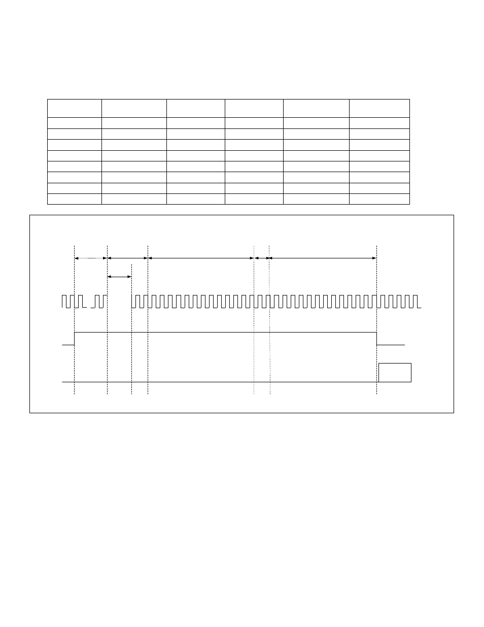
ADACQ[3:0]. Table 7-2 shows the extended acquisition time in terms of core clocks at different ADACQ[3:0] The total
acquisition time, ACQ, is two ADC clocks plus the Extended Acquisition Time (ADACQ, as listed in Table 7-2). Figure 7-4
shows the clocking required for one conversion.
Table 7-2. Extended Acquisition Time in Terms of Core Clock and Time (
s
)
ADACQ[3:0]
# of Core
Clocks
Time (in
s)
ADACQ[3:0]
# of Core
Clocks
Time (in
s)
0
2
0.2
8
1032
103.2
1
6
0.6
9
2056
205.6
2
14
1.4
10
4104
410.4
3
30
3.0
11
8190
819.0
4
62
6.2
12
16382
1638.2
5
126
12.6
13
32766
3276.6
6
254
25.4
14
65534
6553.4
7
520
52.0
15
131070
13107
10 11
1
2
3
4
5
6
7
8
9
18
16
15
14
13
12
28 29
19 20 21 22 23 24 25 26 27
17
30
...
1
19 20
ADACQ
SAMPLE 1
HOLD AND CONVERT SAMPLE 1 SAMPLE 2
HOLD AND CONVERT SAMPLE 2
ADC
STARTUP
ADC DATA
VALID
ADCCLK
ADCONV
ADDATA
Core Clock
delays
(ADACQ[3:0])
Figure 7-4: Extended Acquisition Time
7.1.7
– Location Override
By default, the ADC controller stores ADC conversion results in the ADC buffer location corresponding to the channel
number (as defined in Table 7.1). The ADC controller allows the user to override the default data buffer location and store
the ADC result at any of the buffer location (0-
24). The location override is enabled by setting the LOC_OVR bit to ‘1’ in
the ADCN register. The user has to define the alternate location for storing the ADC conversion result during ADC
configuration (when ADST.ADCFG = 1). The alternate location is defined by ADDATA[12:8] (ALT_LOC). Location override
is demonstrated in Example 7.3.2,
Note: If the location override is used with fixed addresses (as mentioned in 7.1.1), the corresponding peripheral should be
disabled. Example, if the buffer location 20 is used in the ADC sequence with the location override option, the external
remote temperature 1 should be disabled.
7.1.8
– ADC Data Reading
The ADC has a circular data buffer that can hold the results from 25 conversions. When the location override (LOC_OVR
= 0) is disabled, the ADC controller writes the ADC conversion result at the data buffer location corresponding to ADC
channel number, see Table 7-1. When location override is enabled, the ADC controller writes the result to the data buffer