Ds4830 user’s guide, Bit name description, C clock high period – Maxim Integrated DS4830 Optical Microcontroller User Manual
Page 88: C clock low period, 6 – i, 7 – i
DS4830 User’s Guide
88
10.2.5
– I
2
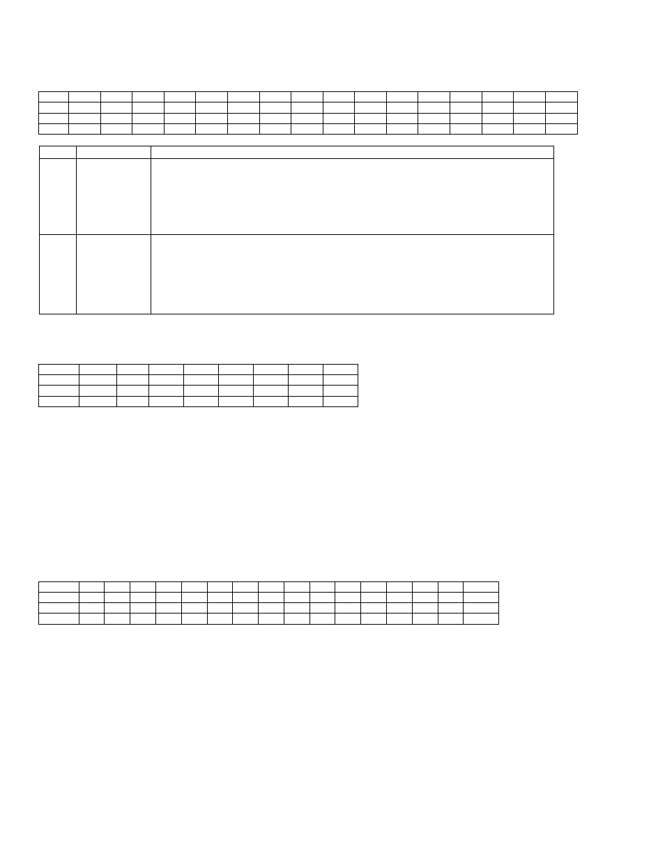
C Master Clock Control Register (I2CCK_M)
Address: M1[0Dh]
Bit
15
14
13
12
11
10
9
8
7
6
5
4
3
2
1
0
Name
I2CCKH7 I2CCKH6 I2CCKH5 I2CCKH4 I2CCKH3 I2CCKH2 I2CCKH1 I2CCKH0 I2CCKL7 I2CCKL6 I2CCKL5 I2CCKL4 I2CCKL3 I2CCKL2 I2CCKL1 I2CCKL0
Reset
0
0
0
0
0
0
1
0
0
0
0
0
0
1
0
0
Access
rw
rw
rw
rw
rw
rw
rw
rw
rw
rw
rw
rw
rw
rw
rw
rw
BIT
NAME
DESCRIPTION
15:8
I2CCKH[7:0]
I
2
C Clock High Period.
These bits define the high period of the
I
2
C
clock. This period
is defined by the number of system clocks. The high time duration is calculated using the
following equation:
I
2
C
High Time Period = System Clock Period x (I2CCKH[7:0] + 1)
I2CCKH[7:0] must be set to a minimum value of 2 to ensure proper operation. Any value
less than 2 will be set to 2.
7:0
I2CCKL[7:0]
I
2
C Clock Low Period.
These bits define the low period of the
I
2
C
clock. This period is
defined by the number of system clocks. The low time duration is calculated using the
following equation:
I
2
C
Low Time Period = System Clock Period x (I2CCKL[7:0] + 1)
I2CCKL[7:0] must be set to a minimum value of 4 to ensure proper operation. Any value
less than 4 will be set to 4.
10.2.6
– I
2
C Master Timeout Register (I2CTO_M)
Address: M1[0Eh]
Bit
7
6
5
4
3
2
1
0
Name
I2CTO7
I2CTO6
I2CTO5
I2CTO4
I2CTO3
I2CTO2
I2CTO1
I2CTO0
Reset
0
0
0
0
0
0
0
0
Access
rw
rw
rw
rw
rw
rw
rw
rw
The I2CTO_M register determines the length of the timeout interval. The timeout interval is defined by the number of I
2
C bit periods
(SCL high + SCL low). When cleared to 00h, the timeout function is disabled. When set to any other value, the
I
2
C
controller waits until
the timeout expires and sets the I2CTOI flag. The timeout period is:
I
2
C
Timeout =
I
2
C
Bit Rate x (I2CTO[7:0] + 1)
The timeout timer resets to 0 and starts to count after each of the following events.
The I2CSTART bit is set.
The I2CSTOP bit is set.
Any time that SCL goes low.
10.2.7
– I
2
C Master Address Register (I2CSLA_M)
Address: M1[0Fh]
Bit
15
14
13
12
11
10
9
8
7
6
5
4
3
2
1
0
Name
-
-
-
-
-
-
-
-
A6
A5
A4
A3
A2
A1
A0
I2CMODE
Reset
0
0
0
0
0
0
0
0
0
0
0
0
0
0
0
0
Access
r
r
r
r
r
r
r
r
rw
rw
rw
rw
rw
rw
rw
rw
This register has no function when operating in master mode.