2 – quick trip register descriptions, Quick trip register descriptions, Ds4830 user’s guide – Maxim Integrated DS4830 Optical Microcontroller User Manual
Page 72
DS4830 User’s Guide
72
9.2
– Quick Trip Register Descriptions
The quick trip has 7 SFRs. These are the Quick Trip Control Register (QTCN), Quick Trip List Register (QTLST), Quick
Trip Data Register (QTDATA), Low Trip Interrupt Flag Register (LTI), High Trip Interrupt Flag Register (HTI), Low Trip
Interrupt Enable Register (LTIE) and High Trip Interrupt Enable Register (HTIE). The QTCN register controls the quick trip
operation. The QTLIST register defines the list for the quick trip controller. The QTDATA register is used to read and write
list and threshold (high and low threshold) registers. The LTI and HTI are interrupt flag registers for high and low
threshold. The LTIE and HTIE are the interrupt enable registers. The Quick Trip SFRs are located in module 5.
9.2.1
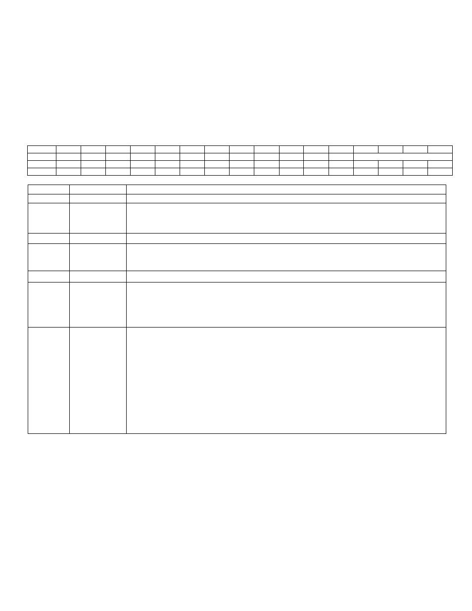
– Quick Trip Control Register (QTCN)
QTCN Register Address: M5 [01h]
Bit
15
14
13
12
11
10
9
8
7
6
5
4
3
2
1
0
Name
-
-
-
QTEN
-
-
-
-
RW_LST
-
-
LTHT
QTIDX[3:0]
Reset
0
0
0
0
0
0
0
0
0
0
0
0
0
0
0
0
Access
r
r
r
rw
r
r
r
r
rw
r
r
rw
rw
rw
rw
rw
BIT
NAME
DESCRIPTION
15:13
-
Reserved. The user should write 0 to these bits.
12
QTEN
Quick Trip Enable.
When this bit is set to ‘1’, it enables the quick trip operation. After
setting the QTEN bit to ‘1’, there is an initial delay for 120 core clock to wake up the quick
trip circuitry. When this bit is set to ‘0’, it disables the quick trip operation.
11:8
-
Reserved. The user should write 0 to these bits.
7
RW_LST
Read List Register:
When this bit is set to ‘1’, it selects one of the sixteen list register
(addressed by QTIDX[3:0], refer below) in the list configuration. When this bit is set to ‘0’,
the low or high threshold register (depends upon the LTHT bit) are configured.
6:5
-
Reserved. The user should write 0 to these bits.
4
LTHT
Low or High Threshold Select:
This bit is used only when RW_LST is set to ‘0’. This bit is
used to select low or high threshold read or write. When the LTHT bit is set to ‘0’, it points
to the low threshold configuration register list. When this bit is set to ‘1’, it points to the high
threshold configuration register list. The address of low or high threshold configuration is
addressed by QTIDX[3:0] bits.
3:0
QTIDX[3:0]
Quick Trip Index Select. These bits together with LTHT and RW_LST bits select the
source or destination address for the QTDATA register access.
When the RW_LST and LTHT
bits are set to ‘0’, the QTIDX[3:0] bits address to one of the
sixteen low threshold register for read or write. When RW_LST = 0 and LTHT = 1, the
QTIDX[3:0] bits address one of the sixteen high threshold register for read or write.
When RW_LST = 1 (irrespective of LTHT bit), the QTDATA register selects the list register
addressed by QTIDX[3:0] bits for read and write operation. A read or write operation on the
QTDATA register will read or write to the list register addressed by QTIDX[3:0].
These bits are auto incremented on any read or write operation to the QTDATA register.
9.2.2
– Quick Trip Data Register (QTDATA)
QTDATA Register Address: M5 [00h]
The Quick Trip Data register is used with LTHT, RW_LST and QTIDX[3:0] bits to configure thresholds and list
configurations. The QTDATA register selects the list register and threshold registers addressed by QTIDX[3:0] bits for
read and write operation.
Threshold registers are sel
ected when the bit RW_LST is set to ‘0’. List registers are selected when the bit RW_LST is set
to ‘1’. Refer below tables for RW_LST = 0 and RW_LST = 1.