Ds4830 user’s guide – Maxim Integrated DS4830 Optical Microcontroller User Manual
Page 74
DS4830 User’s Guide
74
9.2.3
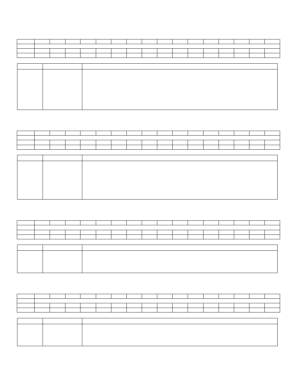
– Low Trip Interrupt Register (LTI)
LTI Register Address: M5 [02h]
Bit
15
14
13
12
11
10
9
8
7
6
5
4
3
2
1
0
Name
IF[15:0]
Reset
0
0
0
0
0
0
0
0
0
0
0
0
0
0
0
0
Access
rw
rw
rw
rw
rw
rw
rw
rw
rw
rw
rw
rw
rw
rw
rw
rw
BIT
NAME
DESCRIPTION
15:0
IF[15:0]
Low Trip Interrupt Flag. The corresponding bit of the Low Trip Interrupt register is set
when a low threshold trip is occurred on a channel list register. In other words, when
voltage across channel is less than the low threshold configuration for the channel.
For Example, if a low trip occurs on the list register 0 then LTI will be set to 0x0001. If the
corresponding bit in the LTIE register is also ‘1’, and then this will generate an interrupt.
Software should clear the Low Trip Interrupt Flag once it is set by hardware. Setting this
bit to ‘1’ by software will generate an interrupt if enabled.
9.2.4
– High Trip Interrupt Register (HTI)
HTI Register Address: M5 [03h]
Bit
15
14
13
12
11
10
9
8
7
6
5
4
3
2
1
0
Name
IF[15:0]
Reset
0
0
0
0
0
0
0
0
0
0
0
0
0
0
0
0
Access
rw
rw
rw
rw
rw
rw
rw
rw
rw
rw
rw
rw
rw
rw
rw
rw
BIT
NAME
DESCRIPTION
15:0
IF[15:0]
High Trip Interrupt Flag. The corresponding bit of the High Trip Interrupt register is set
when a high threshold trip is occurred on a channel list register. In other words, when
voltage across channel is greater than the high threshold configuration for the channel.
For Example, if a high trip occurs on the list register 0 then HTI will be set to 0x0001. If
the corresponding bit
in the HTIE register is also ‘1’, and then this will generate an
interrupt. Software should clear the High Trip Interrupt Flag once it is set by hardware.
Setting this bit to ‘1’ by software will generate an interrupt if enabled.
9.2.5
– Low Trip Interrupt Enable Register (LTIE)
LTIE Register Address: M5 [08h]
Bit
15
14
13
12
11
10
9
8
7
6
5
4
3
2
1
0
Name
IE[15:0]
Reset
0
0
0
0
0
0
0
0
0
0
0
0
0
0
0
0
Access
rw
rw
rw
rw
rw
rw
rw
rw
rw
rw
rw
rw
rw
rw
rw
rw
BIT
NAME
DESCRIPTION
15:0
IE[15:0]
Low Trip Interrupt Enable. This register is used to enable/mask the corresponding LTI
register interrupts. For Example, if LTIE = 0x0001 then Quick Trip list 0 can generate an
interrupt when LTI LSB is set to ‘1’ and all other interrupts from LTI are ignored. Similarly,
if LTIE = 0xFFFF, then all interrupts from LTI will generate interrupts.
9.2.6
– High Trip Interrupt Enable Register (HTIE)
HTIE Register Address: M5 [09h]
Bit
15
14
13
12
11
10
9
8
7
6
5
4
3
2
1
0
Name
IE[15:0]
Reset
0
0
0
0
0
0
0
0
0
0
0
0
0
0
0
0
Access
rw
rw
rw
rw
rw
rw
rw
rw
rw
rw
rw
rw
rw
rw
rw
rw
BIT
NAME
DESCRIPTION
15:0
IE[15:0]
High Trip Interrupt Enable. This register is used to enable/mask the corresponding HTI
register interrupts. For Example, if HTIE = 0x0001 then Quick Trip list 0 can generate an
interrupt when HTI LSB is set to ‘1’ and all other interrupts from HTI are ignored. Similarly,
if HTIE = 0xFFFF, then all interrupts from HTI will generate interrupts.