1 – overview, Section 15, General-purpose input/output (gpio) pins – Maxim Integrated DS4830 Optical Microcontroller User Manual
Page 126: Overview, Ds4830 user’s guide
DS4830 User’s Guide
126
SECTION 15
– GENERAL-PURPOSE INPUT/OUTPUT (GPIO) PINS
15.1
– Overview
The DS4830 provides general-purpose input/output (GPIO) functionality on 31 pins. In addition to the GPIO functionality,
each of these pins is multiplexed with at least one other function, which is classified as “Special Function”.
Special functions override the GPIO register settings of the port pin when they are enabled. Once the special function
takes control, normal control of the port pin is lost until the special function is disabled.
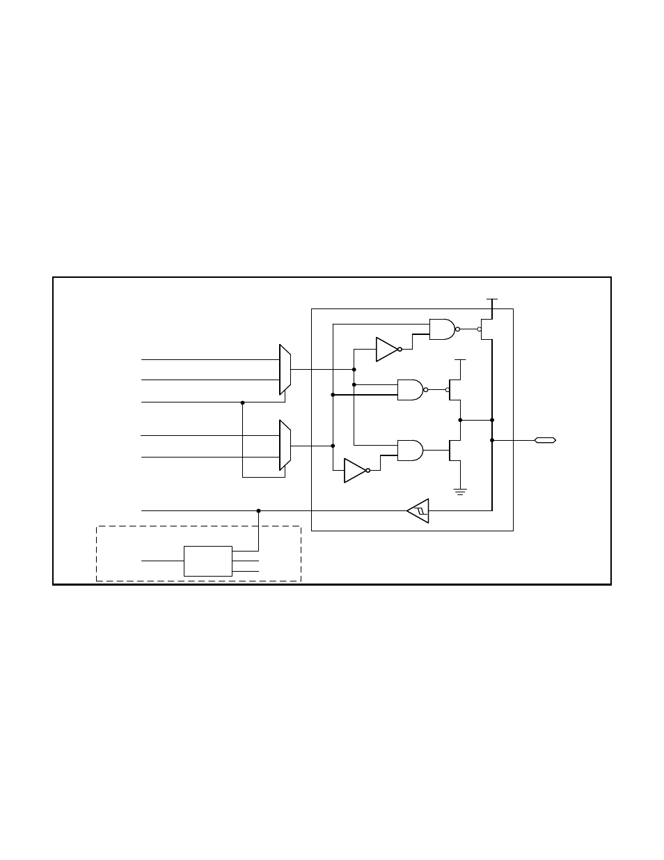
Table 15-1 details all of the GPIO pins as well as what other functions are multiplexed with each pin. With the exception
of a few pins which are described in further detail later, the GPIO pins operate as shown in the GPIO Pin Block Diagram,
Figure 15-1. Some of the features of these GPIO pins are:
CMOS output drivers
Schmitt trigger inputs
Optional weak pullup to VDD when operating in input mode
V
DD
V
DD
M
U
X
I/O PAD
PDp.n
SF DIRECTION
SF ENABLE
POp.n
WEAK
M
U
X
SF OUTPUT
DETECT
CIRCUIT
*
*
DS4830 Pin
SF = SPECIAL FUNCTION
THE FORMAT FOR GPIO CONTROL BITS
SHOWN IS PDp.n
‘p’ designates the port (p=0,1,2,6)
‘n’ is the port pin (n=0 to 7).
PIp.n, or SF INPUT
INTERRUPTS ON ALL PORTS
EIFp.n
EIEp.n
EIESp.n
Figure 15-1
:
GPIO Pin Block Diagram