Section 20 – test access port (tap), Section 20, Test access port (tap) – Maxim Integrated DS4830 Optical Microcontroller User Manual
Page 149: Ds4830 user’s guide, Tap controller
DS4830 User’s Guide
149
SECTION 20
– TEST ACCESS PORT (TAP)
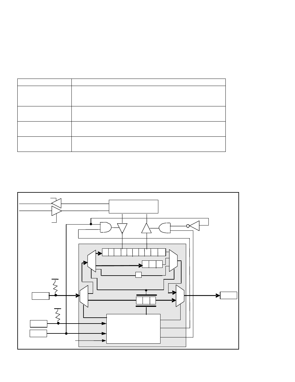
The DS4830 incorporates a Test Access Port (TAP) and TAP controller for communication with a host device across a 4-
wire synchronous serial interface. The TAP may be used by the DS4830 to support in-system programming and/or in-
circuit debug. The TAP is compatible with the JTAG IEEE standard 1149 and is formed by four interface signals described
below. For detailed information on the TAP and TAP controller, refer to IEEE STD
1149.1 “IEEE Standard Test Access
Port and Boundary-Scan Architecture.
”
Table 20-1. Test Access Port Pins
External Pin Signal
Function
TDO
(Test Data Output)
Serial-Data Output. This signal is used to serially transfer internal data to the
external host. Data is transferred least significant bit first. Data is driven out
only on the falling edge of TCK, only during TAP Shift-IR or Shift-DR states
and is otherwise inactive.
TDI
(Test Data Input)
Serial-Data Input. This signal is used to receive data serially transferred by
the host. Data is received least significant bit first and is sampled on the
rising edge of TCK. TDI is weakly pulled high internally when TAP=1.
TCK
(Test Clock Input)
Serial Shift Clock Provided by Host. When this signal is stopped at 0,
storage elements in the TAP logic must retain their data indefinitely. TCK is
weakly pulled high internally when TAP=1.
TMS
(Test Mode Select Input)
Mode Select Input. This signal is sampled at the rising edge of TCK and
controls movement between TAP states. TMS is weakly pulled high internally
when TAP=1.
These pins default to the TAP/JTAG function on reset, which means that the part is always ready for in-circuit debugging
or in-circuit programming operations following any reset. Once an application has been loaded and starts running, the
TAP/JTAG port can still be used for in-circuit debugging operations. If in-circuit debugging functionality is not needed, the
associated port pins can be reclaimed for application use by setting the TAP bit (SC.7) bit to 0. This disables the
TAP/JTAG interface and allows the four pins to operate as normal port pins.
2 1 0
TDO
TDI
WRITE
TCK
DEBUG
UPDATE-DR
UPDATE-DR
V
DD
V
DD
TAP
CONTROLLER
7 6 5 4 3 2 1 0 s1 s0
TMS
SYSTEM PROGRAM
READ
POWER-ON RESET
BY-PASS
0
1
2
INSTRUCTION REGISTER
….
Figure 20-1: TAP and TAP Controller