Ds4830 user’s guide – Maxim Integrated DS4830 Optical Microcontroller User Manual
Page 67
DS4830 User’s Guide
67
8.2.2
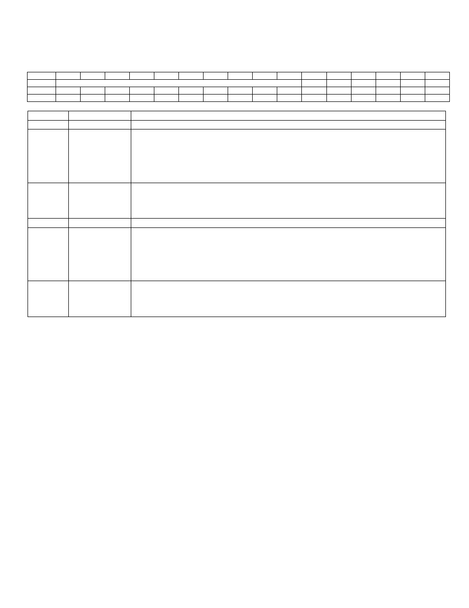
– Sample and Hold Internal Trigger Enable Register (SENR)
SENR Register Address: M2[05h]
Bit
15
14
13
12
11
10
9
8
7
6
5
4
3
2
1
0
Name
INT_TRIG_EN1
INT_TRIG1
-
-
INT_TRIG_EN0
INT_TRIG0
Reset
0
0
0
0
0
0
0
0
0
0
0
0
0
0
0
0
Access
r
r
r
r
r
r
r
r
r
r
rw
rw
r
r
rw
rw
BIT
NAME
DESCRIPTION
15:6
-
Reserved. The user should write 0 to these bits.
5
INT_TRIG_EN1 Sample and Hold 1 Internal Trigger Enable. Setting this bit to ‘1’ will enable internal
trigger mode for Sample and Hold 1. When this bit is set to ‘1’, writing a ‘1’ to INT_TRIG1
will start an internal sample pulse for Sample and Hold 1. When this bit is ‘1’, sample
pulses on SHEN1 are rejected.
Setting this bit to ‘0’ will configure Sample and Hold 1 for external sample pulse.
This bit is used in the dual mode operation only.
4
INT_TRIG1
Sample and Hold 1 Internal Trigger. This bit is used when the INT_TRIG_EN1 is set to
‘1’. Setting this bit to ‘1’ will start internal sample pulse for Sample and Hold 1. Depending
upon the SSC[3:0] bit setting, the sample pulse will stop when this bit is set to ‘0’. This bit
is used in the dual mode operation only.
3:2
-
Reserved. The user should write 0 to these bits.
1
INT_TRIG_EN0 Sample and Hold Internal Trigger Enable. Setting this bit to ‘1’ will enable internal
trigger mode for Sample and Hold 0. When this bit is set to ‘1’, writing a ‘1’ to INT_TRIG0
will start an internal sample
pulse for Sample and Hold 0. When this bit is ‘1’, sample
pulses on SHEN0 are rejected.
Setting this bit to ‘0’ will configure Sample and Hold 0 for external sample pulse.
In the single mode operation, this bit is used for both sample and holds.
0
INT_TRIG0
Sample and Hold0 Internal Trigger. This bit is used when the INT_TRIG_EN0 is set to
‘1’. Setting this bit to ‘1’ will start internal sample pulse for Sample and Hold 0. Depending
upon the SSC[3:0] bit setting, the sample pulse will stop when this bit
is set to ‘0’.
In the single mode operation, this bit is used for both sample and holds.
8.2.3
– Sample and Hold Interrupt flag
See ADST description for Sample and Hold interrupts flags SH0DAI and SH1DAI descriptions.