1 – jtag bootloader protocol, 2 – i2c bootloader protocol, Jtag bootloader protocol – Maxim Integrated DS4830 Optical Microcontroller User Manual
Page 172: I2c bootloader protocol, Ds4830 user’s guide
DS4830 User’s Guide
172
22.2.1
– JTAG Bootloader Protocol
The JTAG port consists of a shift register. As data is clocked into TDI, data will be clocked out of TDO. Each “byte” on
the JTAG port is actually 10 bits. The two least significant bits are the status bits described in Table 22-2. The data that
is input to the device on the TDI pin should have the two status bits set to 0. The following steps are required for each
command.
1) Transmit the Command byte on TDI. Ignore the returned data on TDO.
2) Transmit any Data In bytes on TDI. Ignore the returned data on TDO.
3) Transmit the NOP byte of 00h, on TDI. Ignore the returned data on TDO.
4) Possibly poll returned data until command execution completes.
5) Transmit 00h on TDI for each Data Out byte. Read the Data Out byte on TDO.
6) Transmit 00h on TDI and verify that the Return byte output on TDO is 3Eh.
Some of the bootloader commands, such as the erase and CRC commands require extra time to execute. For these
commands, the two status bits can be used to verify the state of the bootloader. After issuing any of these commands,
the NOP command can continuously be sent to the bootloader. If the returned status bits are 10, the bootloader is still
busy processing the command. If the status bits are 11, the bootloader has completed execution of the command. The
first byte that was returned with status bits 11 will be the first byte of valid returned data from the bootloader.
22.2.2
– I2C Bootloader Protocol
After entering the I
2
C bootloader, all I
2
C communication takes place on the default I
2
C slave address 36h. When writing
data to the DS4830, slave address 36h (R/W bit = 0) is used. To read data from the DS4830 I
2
C bootloader, slave
address 37h (R/W bit = 1) is used. The I
2
C bootloader does not return the status bits that are available from the JTAG
bootloader. The following I
2
C steps are required to send each command
1) Send an I
2
C start, followed by writing slave address 36h (R/W bit set to write).
2) Write command byte.
3) Write any Data In bytes.
4) The NOP byte is not required for the I
2
C interface. Sending a NOP byte when using the I
2
C bootloader will place
the bootloader into an unknown state. Instead, an I
2
C Restart needs to be issued, followed by writing slave
address 37h (R/W bit set to read).
5) Possibly poll returned data until command execution completes.
6) Read and ACK all Data Out bytes.
7) Read and NACK the Return byte, verify that 3Eh was returned.
8) Send an I
2
C stop.
Some of the bootloader commands, such as the erase
and CRC commands require extra time to execute. For these
commands, the I
2
C port can be continuously polled to determine when the command completes. This polling is done by
reading the returned data bytes after sending slave address 37h. The I
2
C bootloader will return data B7h while it is
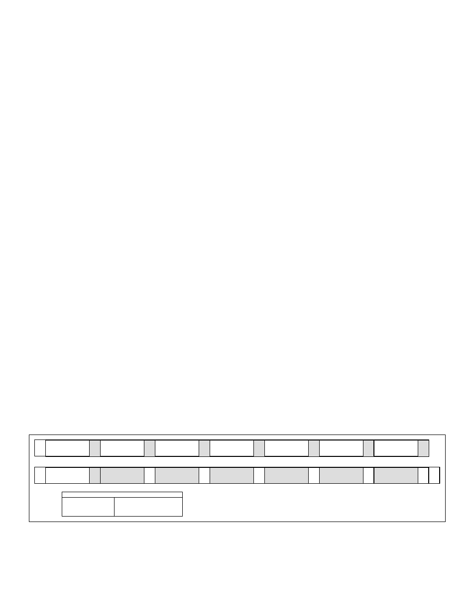
currently busy. When data other than B7h is returned, the bootloader is returning valid data. An example of polling for the
CRC Code command is shown in Figure 22-2. After sending slave address 37h, the I
2
C bootloader will output B7h until
the command has finished execution. The I
2
C master needs to continue reading and returning ACK’s until a string of four
bytes with values B7h, YYh, ZZh, 3Eh is returned. The master then NACK’s this byte (3E).
Command
30h
A
Data In
02h
A
Data In AddrL
00h
A
Data In AddrH
00h
A
Data In LengthL
00h
A
Data In LengthH
01h
A
S
Slave Address(W)
36h
A
Polling
B7h
A
A
Polling
B7h
A
Data Out CRCL
YYh
A
Data Out CRCH
ZZh
A
Return
3Eh
S
R
Slave Address(R)
37h
A
N
A
P
Polling …..
B7h
KEY
S = START
SR = REPEATED START
P = STOP
A = ACKNOWLEDGE
NA = NOT ACKNOWLEDGE
SHADED = SLAVE TRANSACTION
Figure 22-2: I2C Bootloader Polling