2 – adc conversion sequencing, Adc conversion sequencing, Ds4830 user’s guide – Maxim Integrated DS4830 Optical Microcontroller User Manual
Page 47
DS4830 User’s Guide
47
By default, the external channels GP0-15 are general-purpose input. The DS4830 has the Pin Select Register (PINSEL).
The PINSEL register is used to configure the external channels as an analog pin for ADC or/and Quick Trip use. Each bit
location in this register corresponds to the ADC/Quick Trip input pin.
The ADC controller uses a set of Special Function Registers (SFRs) to configure the ADC for the desired mode of
operation. The DS4830 ADC can operate in the three modes mentioned below.
1. ADC Sequence Mode Conversions
2. Temperature Mode Conversions
3. Sample and Hold Mode Conversions
7.1.2
– ADC Conversion Sequencing
The ADC controller provides 24 ADC configuration registers. The DS4830 ADC controller performs a user defined
sequence for up to 16 single ended or 8 differential external voltage channels. Additionally, the ADC controller allows the
user to add the DAC external references (REFINA and REFINB), the DAC internal reference, and VDD to the sequence.
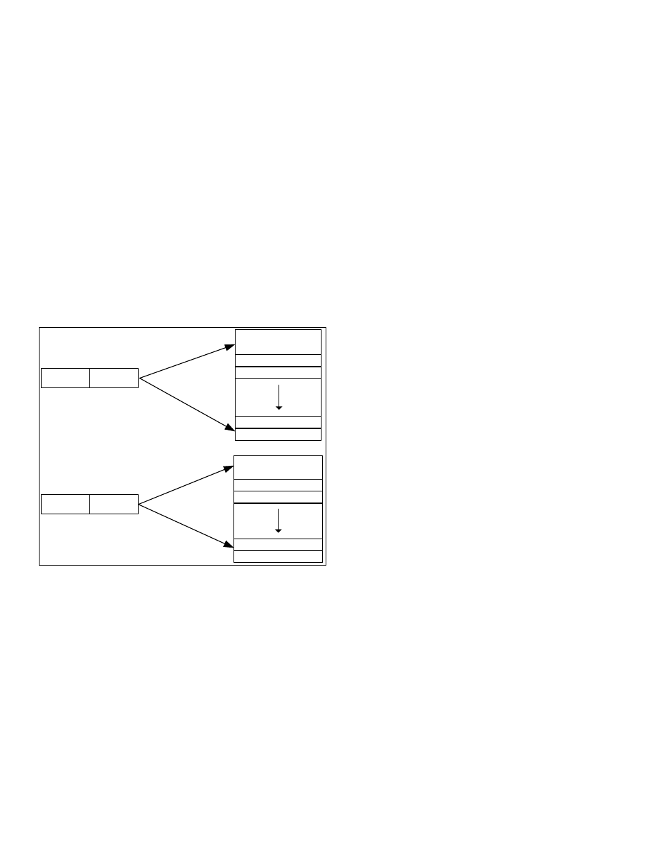
The configuration registers are accessed by writing to the ADDATA register when ADST.ADCFG = 1. Each conversion in
a sequence is setup using one of the ADC configuration registers. The results from the ADC converter are located in the
25 data buffers. These are accessed by reading from the ADDATA register when ADST.ADCFG = 0. See Figure 7-2 for
ADC configurations and data buffers.
ADCFG = 0
Data Buffer[0]
Data Buffer[23]
Data Buffer[1]
Data Buffer[24]
DATA BUFFERS
CONFIGURATION[0]
CONFIGURATION[22]
CONFIGURATION[1]
CONFIGURATION[23]
ADC CONFIGURATIONS
ADIDX[4:0]
ADCFG = 1
ADIDX[4:0]
Figure 7-2: ADC Configurations and Data Buffers
Note: With location override enabled, a single channel can be added multiple times as demonstrated in Example 7.3.2.
The configuration register pointed to by ADDATA is selected using the ADIDX bits in the ADST register when ADCFG = 1.
The individual configuration registers allows each of the conversions in a sequence to select from the following options.
ADC channel selection
Differential or single ended conversion
Full scale range
Extended acquisition enable
ADC conversion data alignment (left or right)
Alternate location
For more information, see the Configuration Register description for the ADDATA register.
A sequence is setup in the ADC Address register (ADADDR) by defining the starting conversion configuration address
(ADSTART) and an ending conversion configuration address (ADEND). The configuration start address designates the
configuration register to be used for the first conversion in a sequence. The configuration end address designates the
configuration register used for the last conversion in a sequence. A single channel conversion can be viewed as a special