14 - command 21h – dump data, 15 - command 30h – crc code, 16 - command 31h – crc data – Maxim Integrated DS4830 Optical Microcontroller User Manual
Page 177: 17 - command 40h – verify code, 18 - command 41h – verify data, 14 - command 21h, Dump data, 15 - command 30h, Crc code, 16 - command 31h
DS4830 User’s Guide
177
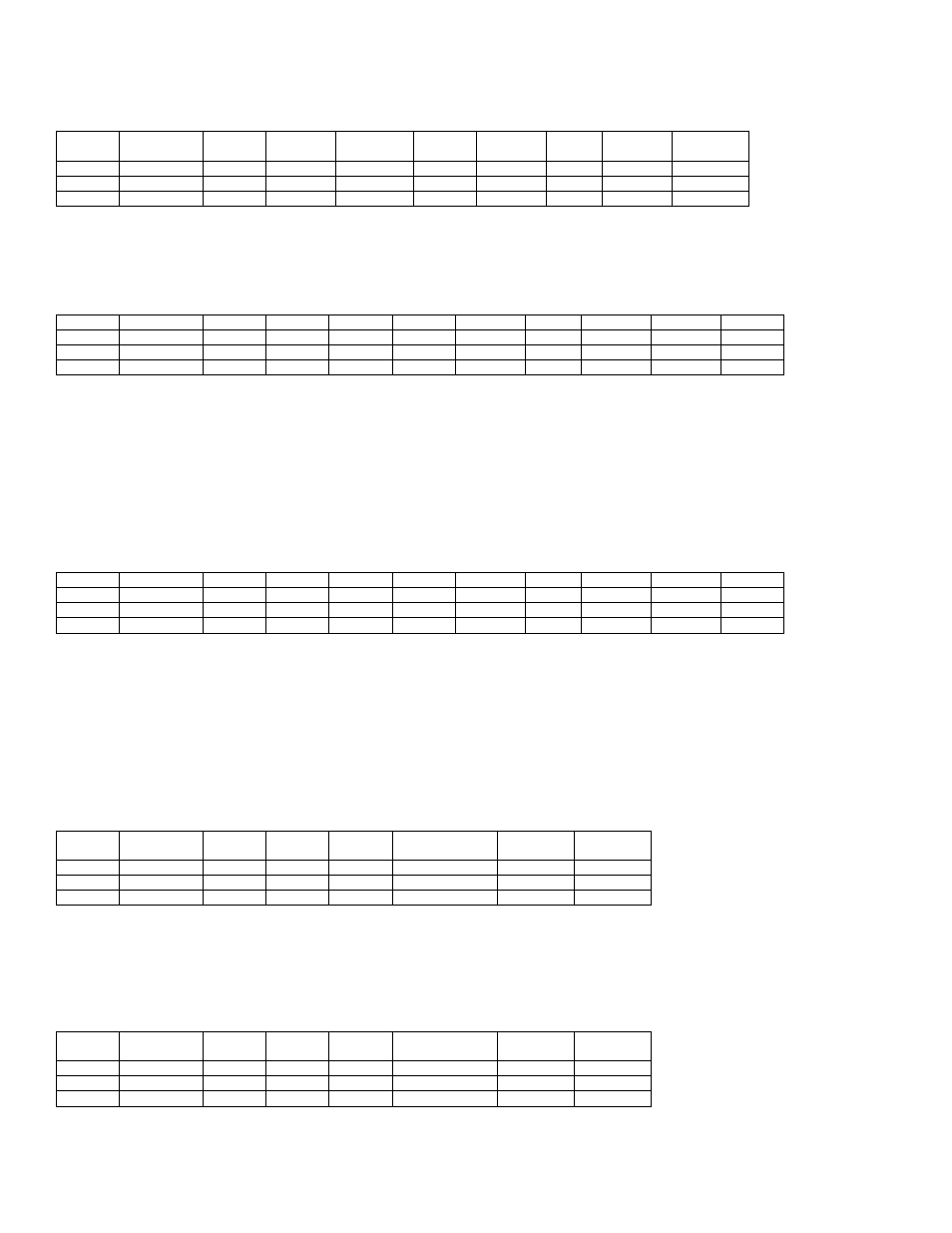
22.3.14 - Command 21h
– Dump Data
Byte 1
Byte 2
Byte 3
Byte 4
Byte 5
Byte 5
Byte 6
Length
Bytes
Byte
Length+7
Command
Data In
Data In
Data In
Data In
Data In
NOP
Data Out
Return
Input
21h
2
AddrL
AddrH
LengthL
LengthH
00h
00h
00h
Output
X
X
X
X
X
X
X
Memory
3Eh
This command returns the contents of the SRAM memory. The memory dump begins at byte address AddrH:AddrL and
will contain LengthH:LengthL bytes. This command is password protected.
22.3.15 - Command 30h
– CRC Code
Byte 1
Byte 2
Byte 3
Byte 4
Byte 5
Byte 6
Byte 7
Byte 8
Byte 9
Byte 10
Command
Data In
Data In
Data In
Data In
Data In
NOP
Data Out
Data Out
Return
Input
30h
2
AddrL
AddrH
LengthL
LengthH
00h
00h
00h
00h
Output
X
X
X
X
X
X
X
CRCL
CRCH
3Eh
This command returns the CRC-16 value (CRCH:CRCL) of the (LengthH:LengthL) bytes of program flash starting at
(AddrH:AddrL). The formula for the CRC calculation is X
16
+ X
15
+ X
2
+ 1. This command is password protected.
The CRC calculation takes approximately 45 system clock cycles per byte. During this time polling should be performed
to determine when the loader has finished executing the CRC calculation. If using the I
2
C loader, use the polling method
shown in Figure 22-2. When a data string is read that has B7, CRCL, CRCH, 3Eh, the host will know that the calculation
completed successfully. If using the JTAG loader, the JTAG status bits can be used to determine when the CRC
calculation is complete.
22.3.16 - Command 31h
– CRC Data
Byte 1
Byte 2
Byte 3
Byte 4
Byte 5
Byte 6
Byte 7
Byte 8
Byte 9
Byte 10
Command
Data In
Data In
Data In
Data In
Data In
NOP
Data Out
Data Out
Return
Input
31h
2
AddrL
AddrH
LengthL
LengthH
00h
00h
00h
00h
Output
X
X
X
X
X
X
X
CRCL
CRCH
3Eh
This command returns the CRC-16 value (CRCH:CRCL) of the (LengthH:LengthL) bytes of data memory starting at
(AddrH:AddrL). The formula for the CRC calculation is X
16
+ X
15
+ X
2
+ 1. This command is password protected.
The CRC calculation takes approximately 45 system clock cycles per byte. During this time polling should be performed
to determine when the loader has finished executing the CRC calculation. If using the I
2
C loader, use the polling method
shown in Figure 22-2. When a data string is read that has B7, CRCL, CRCH, 3Eh, the host will know that the calculation
completed successfully. If using the JTAG loader, the JTAG status bits can be used to determine when the CRC
calculation is complete.
22.3.17 - Command 40h
– Verify Code
Byte 1
Byte 2
Byte 3
Byte 4
(Length) Bytes
Byte
Length+5
Byte
Length+6
Command
Data In
Data In
Data In
Data In
NOP
Return
Input
40h
Length
AddrL
AddrH
Data to Verify
00h
00h
Output
X
X
X
X
X
X
3Eh
This command operates in the same manner as the Load Code command, except that instead of programming the input
data into flash memory, it verifies that the input data matches the data already in code space. If the data does not match,
the status code is set to reflect this failure. This command is password protected.
22.3.18 - Command 41h
– Verify Data
Byte 1
Byte 2
Byte 3
Byte 4
(Length) Bytes
Byte
Length+5
Byte
Length+6
Command
Data In
Data In
Data In
Data In
NOP
Return
Input
41h
Length
AddrL
AddrH
Data to Verify
00h
00h
Output
X
X
X
X
X
X
3Eh