5 – hardware multiplier peripheral registers, Hardware multiplier peripheral registers, Ds4830 user’s guide – Maxim Integrated DS4830 Optical Microcontroller User Manual
Page 142
DS4830 User’s Guide
142
The specified hardware multiplier operation begins when the final operand(s) is loaded and will complete in a single cycle.
The read-only MC1R, MC0R result registers can be accessed in the very next cycle unless accumulation/subtraction with
MC2:0 is requested (MCW = 0 and MMAC = 1), in which case, one cycle is required so that stable data can be read.
When MCW = 0, the MC2:0 registers always require one wait cycle before the operation result is accessible. The single
wait cycle needed for updating the MC2:0 registers with a calculated result does not prevent initiating another calculation.
Back-to-back operations can be triggered (independent of data type and operand count) without the need of wait state
between the loadings of operands.
Table 18-1 Hardware Multiplier Operations
MCW:MSUB:MMAC
OPERATION
MC2
MC1
MC0
MC1R:MC0R
OF STATUS
000
Multiply
MA*MB
MA*MB
No
001
Multiply-Accumulate
MC+(MA*MB)
32lsbits of (MC+2*(MA*MB))
Yes
010
Multiply-Negate (SUS = 0 only)
-(MA*MB)
-(MA*MB)
No
011
Multiply-Subtract
MC-(MA*MB)
32lsbits of (MC-2*(MA*MB))
Yes
100
Multiply
MC2
MC1
MC0
MA*MB
No
101
Multiply-Accumulate
MC2
MC1
MC0
32lsbits of (MC+(MA*MB))
No
110
Multiply-Negate (SUS = 0 only)
MC2
MC1
MC0
-(MA*MB)
No
111
Multiply-Subtract
MC2
MC1
MC0
32lsbits of (MC-(MA*MB))
No
18.5
– Hardware Multiplier Peripheral Registers
The hardware multiplier registers are detailed below. Addresses of registers are given as “Mx[yy]” where x is the module
number (from 0 to 5 decimal) and yy is the register index (from 00h to 1Fh hexadecimal).
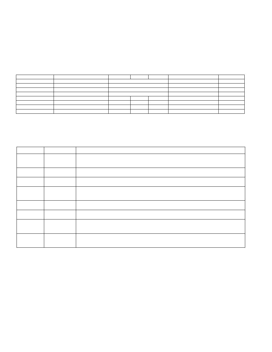
Table 18-2 Hardware Multiplier Registers
Register
Address
Function
MCNT
M3[00h]
Multiplier Control Register. Selects operation, data type, operand count, hardware square
function, and write option on the MC register. Also contains the overflow flag and the clear
control for operand registers and accumulator.
MA
M3[01h]
Multiplier Operand A Register. Used by the user software to load one of the 16-bit values for
a hardware multiplier operation.
MB
M3[02h]
Multiplier Operand B Register. Used by the user software to load one of the 16-bit values for
a hardware multiplier operation.
MC2
M3[03h]
Multiplier Accumulate Register 2. Contains the two most significant bytes of the accumulator
register. The 48-bit accumulator is formed by MC2, MC1 and MC0. The most significant bit
of this register is the signed bit for signed operations.
MC1
M3[04h]
Multiplier Accumulate Register 1. Contains bytes 3 and 2 of the accumulator register. The
48-bit accumulator is formed by MC2, MC1 and MC0.
MC0
M3[05h]
Multiplier Accumulate Register 0. Contains the two least significant bytes of the accumulator
register. The 48-bit accumulator is formed by MC2, MC1 and MC0.
MC1R
M3[08h]
Multiplier Read Register 1. Contains bytes 1 and 0 result from the last operation when MCW
bit is 1 or the last operation is either multiply-only or multiply-negate. The contents of this
register will remain until an SFR related to the multiplier has been changed.
MC0R
M3[09h]
Multiplier Read Register 0. Contains bytes 3 and 2 result from the last operation when MCW
bit is 1 or the last operation is either multiply-only or multiply-negate. The contents of this
register will remain unchanged until an SFR related to the multiplier has been changed.