4 – timeout, Timeout, Ds4830 user’s guide – Maxim Integrated DS4830 Optical Microcontroller User Manual
Page 77
DS4830 User’s Guide
77
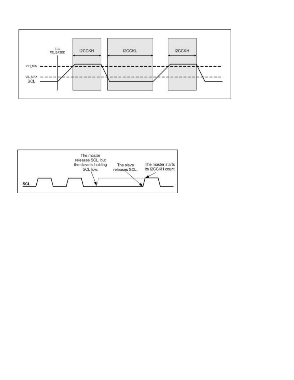
Figure 10-1: I
2
C Clock Generation
The master I
2
C controller’s ability to monitor the state of SCL allows the master to operate with slave devices that clock
stretch. A slave device may clock stretch, or hold SCL low, while it is busy or processing data. The master I
2
C controller
will always release SCL after holding it low for the SCL Low Time duration. By monitoring the state of SCL, the master I
2
C
controller realizes that SCL has not been released and does not begin the SCL High Time count. Only after the master
controller detects a high state on SCL will it begin the I2CCKH count. This is illustrated in Figure 10-2.
Figure 10-2: Master I
2
C Clock Generation during Slave Clock Stretching
10.1.4
– Timeout
The Master I
2
C Controller has a programmable timeout function that allows the controller to recover from a bus error.
The timeout period is determined by the setting of the I
2
C Master Timeout Register (I2CTO_M) using the following
equation
Timeout Period = I
2
C Bit Rate x (I2CTO[7:0]+1)
where I
2
C Bit Rate is determined by the setting of the I2CCK_M register. The timeout can be disabled by clearing the
I2CTO_M register to 0. The I
2
C timeout timer starts counting:
When the I2CSTART bit is set to 1. The I
2
C controller will monitor the bus status until it can generate a
START condition. The I
2
C bus is considered busy if another master has generated a START condition and
no corresponding STOP has been detected (the I2CBUS bit is set to 1) or the SCL line is low. If the bus
remains busy for a period longer than specified in the timeout register, the I
2
C controller concludes that there is
a bus error and will set the I2CTOI flag.
If the I
2
C Controller has started a transfer (after the 1
st
bit rising edge), it will wait for the current byte transfer
to finish (after the 9
th
bit (acknowledge) has been transmit) before generating the START condition. In this
case, the timeout timer will start counting after the end of the 9
th
bit low time.
After the master I
2
C controller attempts to generate a STOP condition. If a STOP is not detected (I2CSPI = 1)
during the timeout period, the I2CTOI flag will be set.
If the I2C Controller has started a transfer (after the 1st bit rising edge), it will wait for the current byte transfer to finish
(after the 9th bit (acknowledge) has been transmit) before generating the STOP condition. In this case, the timeout
timer will start counting after the end of the 9th bit low time.