Ds4830 user’s guide – Maxim Integrated DS4830 Optical Microcontroller User Manual
Page 124
DS4830 User’s Guide
124
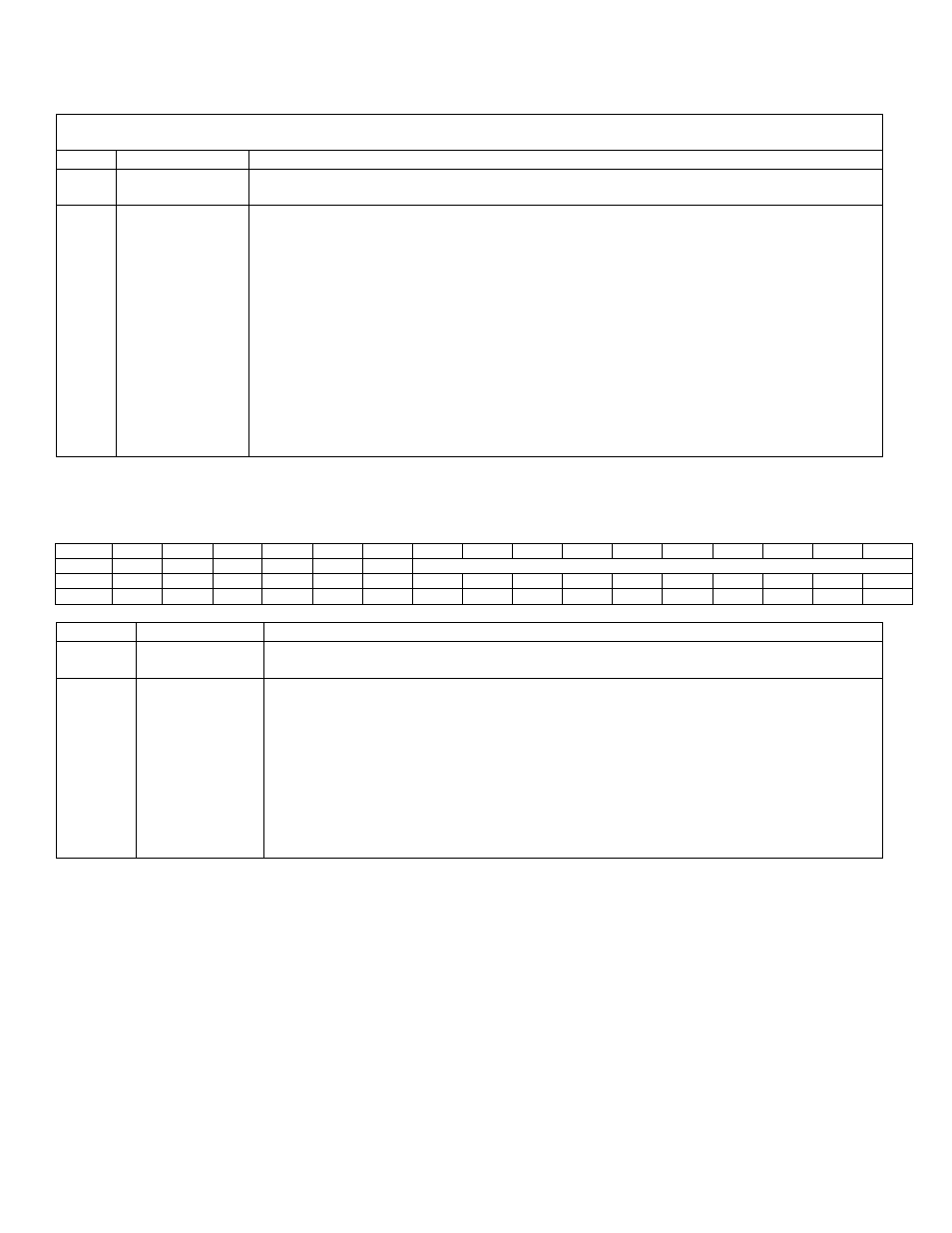
14.3.2.3
– Local Register PWMDLYn
PWMCN REG_SEL = 1xb
PWMDATA[15:0] PWMDLY[15:0]
BIT
NAME
DESCRIPTION
15:12
Reserved
Reserved. The user should not write to these bits.
These bits are ignored by the PWM controller.
11:0
PWMDLYn[11:0] Delay Setting Register. When REG_SEL[1:0] is set to 1xb, the PWMDATA register
points to the Delay Setting Register of PWM channel selected by PWM_SEL[3:0] bits in
the PWMCN register. The Delay Setting Register is a 12-bit register, which is used for
providing starting delay. Using this Delay Setting Register multiphase operation can be
configured.
If PWM_SEL[3:0] = 0101b and REG_SEL[1:0] = 1xb, then the PWMDATA register points
to the Delay Register of the PWM Channel 5. A read or write to/from the PWMDATA
register will read or write from the Duty Setting Register of PWM Channel 5.
The Delay Setting Register is 12-bit register but number of bits is used by the PWM
controller depends upon the selected resolution for given PWM channel. For Example, if
resolution is 9- bits then only lower 9 bits PWMDLYn[8:0] are used in PWM operation and
upper bits 10-15 bits will be ignored..
14.3.3
– PWM Synchronization Register (PWMSYNC)
PWMSYNC Register Address: M5 [07h]
Bit
15
14
13
12
11
10
9
8
7
6
5
4
3
2
1
0
Name
-
-
-
-
-
-
PWMSYNC[9:0]
Reset
0
0
0
0
0
0
0
0
0
0
0
0
0
0
0
0
Access
r
r
r
r
r
r
rw
rw
rw
rw
rw
rw
rw
rw
rw
rw
BIT
NAME
DESCRIPTION
15:10
Reserved
Reserved. The user should write 0 to these bits. These bits are ignored by the PWM
controller.
9:0
PWMSYNC[9:0] PWM Synchronization. This register is used to provide synchronization among
different PWM channels. Each bit of this register corresponds to a PWM channel.
Setting any bit of this register will restart corresponding PWM channel. After a write to
this register, it is cleared to 0x0000 on the next core cycle.
For Example, When 0x0005 is written on the PWMSYNC register, PWM channel 0 and
2 will restart after current PWM counter (internal register) is over. This feature is used
to bring different PWM channels in phase if they have the same PWM configurations
(Resolution, Clock source, and Pulse spreading configuration etc). The Delay Register
settings can be different for the PWM channels to be synchronized, and the settings
are retained after the synchronization. See Figures 14.2 and 14.7 for details.