Section 18 – hardware multiplier module, 1 – hardware multiplier organization, 2 – hardware multiplier controls – Maxim Integrated DS4830 Optical Microcontroller User Manual
Page 140: Section 18, Hardware multiplier module, Hardware multiplier organization, Hardware multiplier controls, Multiplier
DS4830 User’s Guide
140
SECTION 18
– HARDWARE MULTIPLIER MODULE
The hardware multiplier module can be used by the DS4830 to support high-speed multiplications. The hardware
multiplier module is equipped with two 16-bit operand registers, a 32-bit read-only result register, and an accumulator of
48-bit width. The multiplier can complete a 16-bit x 16-bit multiply-and-accumulate/subtract operation in a single cycle.
The hardware multiplier module supports the following operations without interfering with the normal core functions:
o Signed or unsigned Multiply (16 bit x 16 bit)
o Signed or unsigned Multiply-Accumulate (16 bit x 16 bit)
o Signed or unsigned Multiply-Subtract (16 bit x 16 bit)
o Signed Multiply and Negate (16 bit x 16 bit)
18.1
– Hardware Multiplier Organization
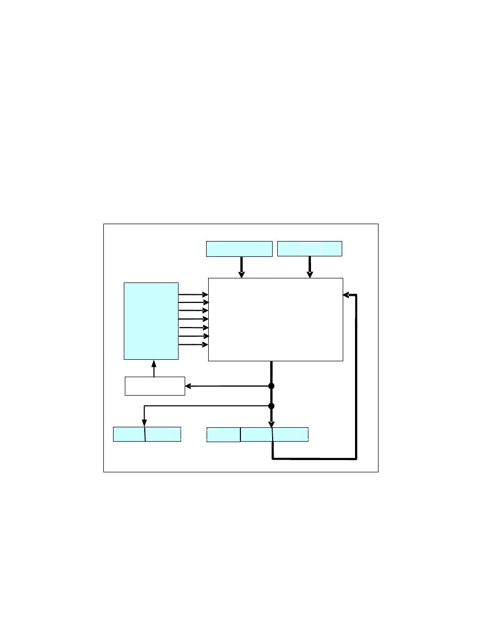
The hardware multiplier consists of two 16-bit, parallel-load operand registers (MA, MB); a read-only result register formed by two
parallel 16-bit registers (MC1R and MC0R); an accumulator, which is formed by three 16-bit parallel registers (MC2, MC1, and MC0);
and a status/control register (MCNT). Figure 18-1 shows a block diagram of the hardware multiplier.
Figure 18-1
:
Multiplier Organization
18.2
– Hardware Multiplier Controls
The selection of operation to be performed by the multiplier is determined by four control bits in the MCNT register: SUS,
MSUB, MMAC, and SQU. The number of operands that must be loaded to trigger the specified operation is dictated by
the OPCS bit setting, except when the square function is enabled (SQU = 1). Enabling the square function implicitly
defines that only a single operand (either MA or MB) needs to be loaded to trigger the square operation, independent of
the OPCS bit setting. The MCNT register bits must be configured to select the desired operation and operand count prior
to loading the operand(s) to trigger the multiplier operation. Any write to MCNT automatically resets the operand load
counter of the multiplier, but does not affect the operand registers, unless such action is requested using the Clear Data
Registers (CLD) control bit. Once the desired operation has been specified via the MCNT register bits, loading the
prescribed number of operands triggers the respective multiply, multiply-accumulate/subtract or multiply-negate operation.
MA
MB
MC0
MC1
MC2
MULTIPLIER
0
0
15
15
0
15
0
15
0
15
MCNT
Overflow
SUS
MMAC
OPCS
SQU
MSUB
CLD
MCW
MC0R
MC1R
0
15
0
15